00198171-02_Technical_Training_FSE_TX-Series_EN.pdf - 第110页
7 Power Supply 7.11 Analysis - Common Error List 110 Technical Training FSE SIPLACE TX-Series 01/2018 7.11 Analysis - Common Error List Error Possible Cause Action No reaction after START pressed Duration of pressing and…
7 Power Supply
7.10 I / O Control Unit Distributor
Technical Training FSE SIPLACE TX-Series 01/2018 109
X 8 Data Output DO8 to DO15:
DO_8 Reserved (X37-12)
DO_9 Buzzer (X32-5)
DO_10 Indicator_1_RD Red Light tower_1 lights with “High“ at Port Out-
put
(X32-4)
DO_11 Indicator_2_RD Red Light tower_2 lights with “High“ at Port Out-
put
(X32-9)
DO_12 Indicator_1_GNThe green Light tower_1 lights with “High“ at Port
Output
(X32-1)
DO_13 Indicator_2_GNThe green Light tower_2 lights with “High“ at Port
Output
(X32-2)
DO_14 Indicator_1_YEThe yellow Light tower_1 lights with “High“ at Port
Output
(X32-7)
DO_15 Indicator_2_YEThe yellow Light tower_2 lights with “High“ at Port
Output
(X32-6)
X 17 Data Output DO16 to DO23:
DO_16 Service for integration tests (X25-9)
DO_17 Service for integration tests (X25-11)
DO_18 Service for integration tests (X25-12)
DO_19 Reserved
DO_20 Reserved
DO_22 Reserved
DO_23 Reserved
DO_24 Reserved
Data exchange with the power supply unit SMPS
The interface allows data exchange with the power modules of the SMPS (Switched Mode Power
Supply). For example voltages dips from the customer main net can be seen at the station soft-
ware.
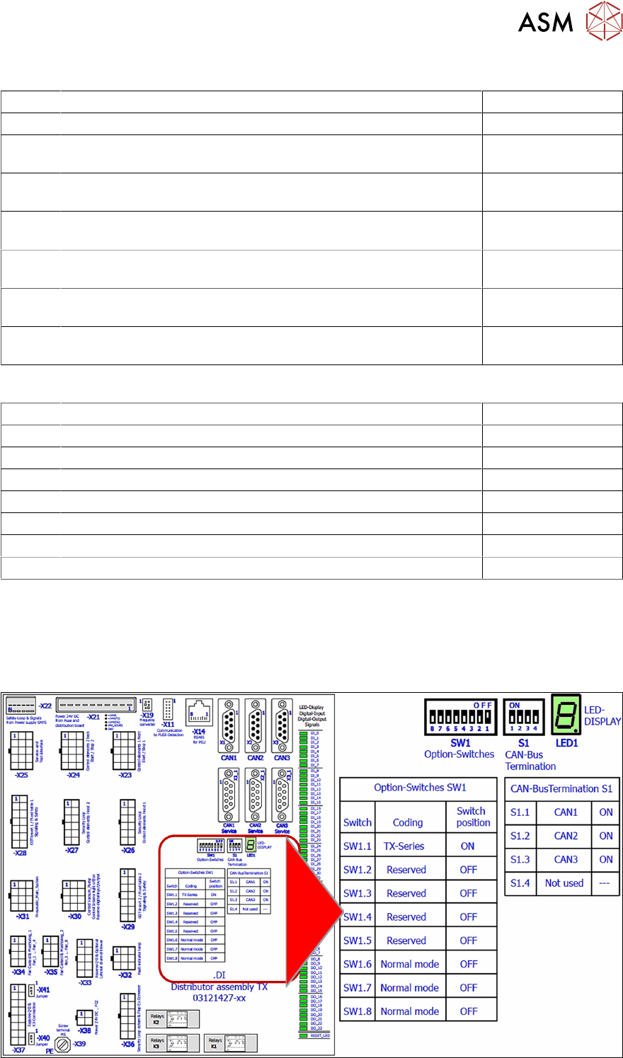
I/O Distributor Assembly DIP Switches
7 Power Supply
7.11 Analysis - Common Error List
110 Technical Training FSE SIPLACE TX-Series 01/2018
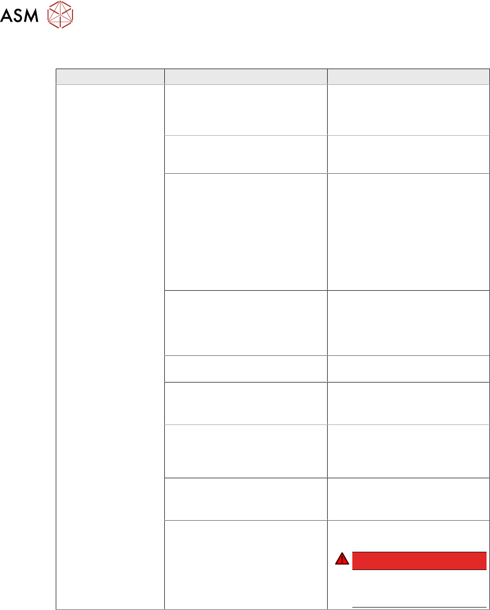
7.11 Analysis - Common Error List
Error Possible Cause Action
No reaction after
START pressed
Duration of pressing and release of
START button
●
Press longer than 200 ms and
shorter than 1500 ms.
START should be accepted on
pushbutton release.
Safety loop closed?
●
Check if both channels of
safety loop show closed con-
dition
SW_CTRL_ON output of IO miss-
ing?
●
Check: (X29.A6) should be
HIGH if START is pressed
●
Check IO wiring.
●
Check IO output.
●
Check START button wiring.
If output is missing:
●
Replace IO unit
●
Fix START button wiring.
Connection to PCB FD.A1 estab-
lished?
●
Check connectors X24A and
X24B at FD.A1 and at PCB
CSB
●
Place connectors firm in posi-
tion.
Ground connection of PCB CSB
missing?
●
Connect terminal lug to
Ground terminal of CSB.
Supply voltage of CSB missing?
●
Check fuses F12 and F13.
●
Replace fuses F12 and F13, if
needed.
Signal PCC-POWER-OK (X24B.5
at PCB,LED at K5)
If voltage reading > 22V or Power
OK LED of K5 is on→ internal de-
fect of CSB:
●
Replace unit
24V Measure input voltage
(X24B.3)
If voltage reading > 22V → internal
defect of CSB:
●
Replace unit
Power connectors of CAP and CSB Connectors should be firm in posi-
tion.
DANGER!
If you check connectors
mind the dangerous
voltage!
.

7 Power Supply
7.11 Analysis - Common Error List
Technical Training FSE SIPLACE TX-Series 01/2018 111
Error Possible Cause Action
Short reaction of CSB
after START pressed
●
Check precharge current at
300 V DC link voltage
If there is no precharge current
(max 10A):
●
Check GND connection of
CSB
Ground connection of PCB CSB
missing?
●
Connect terminal lug to
Ground terminal of CSB.
If there is GND connection estab-
lished:
→ internal defect of CSB;
●
Replace unit
Overload or short circuit at 160 V
DC link output?
●
Remove X24B and try to start.
If Start is working now fix short cir-
cuit conditions at 160V DC link
branch
Overload or short circuit at 300 V
DC link voltage?
●
Remove X21 and X22 and try
to start.
If Start is working now fix short cir-
cuit conditions at 300V DC link
branch
Machine is passing ref-
erence run but stops at
beginning the of pro-
duction run
MGCU Error Message: Under-
voltage error at DC link voltage?
●
Check capacitor value of CAP
unit (service screen of dia-
gnostic functions) has to be >
30 mF
If Capacitor value < 30 mF:
●
Replace capacitor unit
●
Check QT40.999 error mes-
sages at service screen
If QT40 error is shown:
●
Replace QT40 unit.
Service screen QT40 unit
●
Check indicator lights at
QT40-999:
Green light (>220V) should be on
during reference run
red light should be on temporary
during gantry acceleration period
DC 42V-S is missing
(Conveyor supply)
Fuse does not work?
Connector X24A (both PCB’s!)
properly connected?
●
Check supply voltage at
FD.A1, F16
Fuse blown or broken?
●
Replace fuse
●
Place connector firm into
place
If error still occurs
→ internal defect of CS:
●
Replace unit