00198171-02_Technical_Training_FSE_TX-Series_EN.pdf - 第89页
7 Power Supply 7.3 Voltage Overview Block diagrams Technical Training FSE SIPLACE TX-Series 01/2018 89 7.3 Voltage Overview Block diagrams 7.3.1 Circuit Diagram of Power Supply TX The diagram above shows a simple overvie…
7 Power Supply
7.2 Wiring colour description
88 Technical Training FSE SIPLACE TX-Series 01/2018
Voltage Colour Code Comment
GND, 0 V White WH
Control general Yellow YE Control, Inputs, Outputs, Emergency
stop
7 Power Supply
7.3 Voltage Overview Block diagrams
Technical Training FSE SIPLACE TX-Series 01/2018 89
7.3 Voltage Overview Block diagrams
7.3.1 Circuit Diagram of Power Supply TX
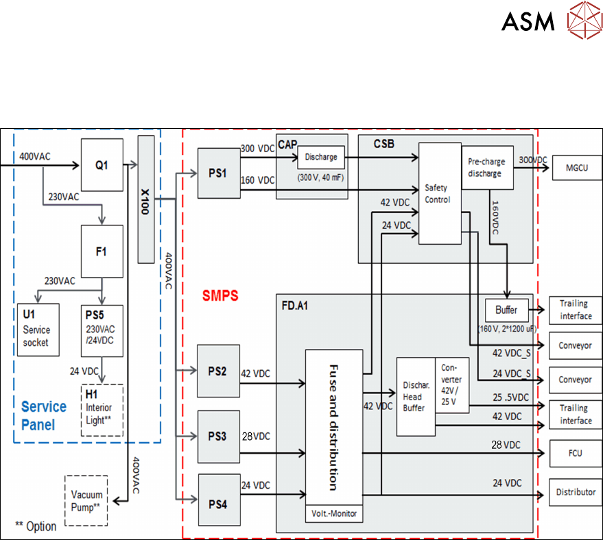
The diagram above shows a simple overview of the voltage generation with the SMPS.
●
The power pack PS1 converts the mains input AC voltage into 300VDC (for intermediate cir-
cuit voltage man axes) and 160VDC (for intermediate circuit voltage head axis).
●
The 300VDC is run via the backup battery CAP1 to the CSB (Contactor-based Safety
Breaker) the voltage is charged/discharged in a controlled manner via the pre/discharge board
A2 and the energy is backed up by the backup battery CAP1.
●
The power pack PS2 converts the mains input AC voltage into 42VDC.
●
One link of the 42VDC voltage is run via the CSB from where it is then run back to the FDB
and distributed as 42VDC_S (switched).The other link is directly to the discharge head buffer.
●
The power pack PS3 converts the mains input AC voltage into 28VDC.
●
The power pack PS4 converts the mains input AC voltage into 24VDC.
●
This 24VDC voltage is run via the CSB, from where it is then run back to the FDB and distrib-
uted as 24VDC_S (switched).
●
All voltages are protected by the Fuse & Distribution Board (FDB).
7 Power Supply
7.3 Voltage Overview Block diagrams
90 Technical Training FSE SIPLACE TX-Series 01/2018
7.3.2 300 V Intermediate Circuit Voltage for Main Axes
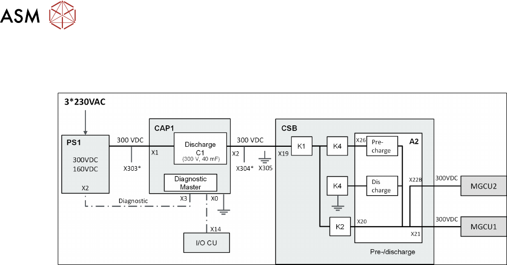
The following diagram illustrates the generation of the 300V intermediate circuit current for the
main axes.
* X303/X304 Service Testing point for DC 300V in/out
●
The 300VDC intermediate circuit voltage for the main axes is generated with the PS1 power
pack and is emitted directly via the CAP1 and the CSB assembly to the MGCU.
●
The capacitor battery CAP1 is charged with this 300VDC.
●
The control of pre-charging and discharging of the main axes in connection with the energy
management in the backup battery is managed by the pre/discharge board -A2 in the safety
breaker assembly (CSB).