00198171-02_Technical_Training_FSE_TX-Series_EN.pdf - 第97页
7 Power Supply 7.5 Overview of Fuse board FD:A1 Technical Training FSE SIPLACE TX-Series 01/2018 97 7.5 Overview of Fuse board FD:A1 1. Connector to CSB unit 5. 42V head buffer caps 9. Head Boost converter in- put 42VDC …
7 Power Supply
7.4 CAP Function Description
96 Technical Training FSE SIPLACE TX-Series 01/2018
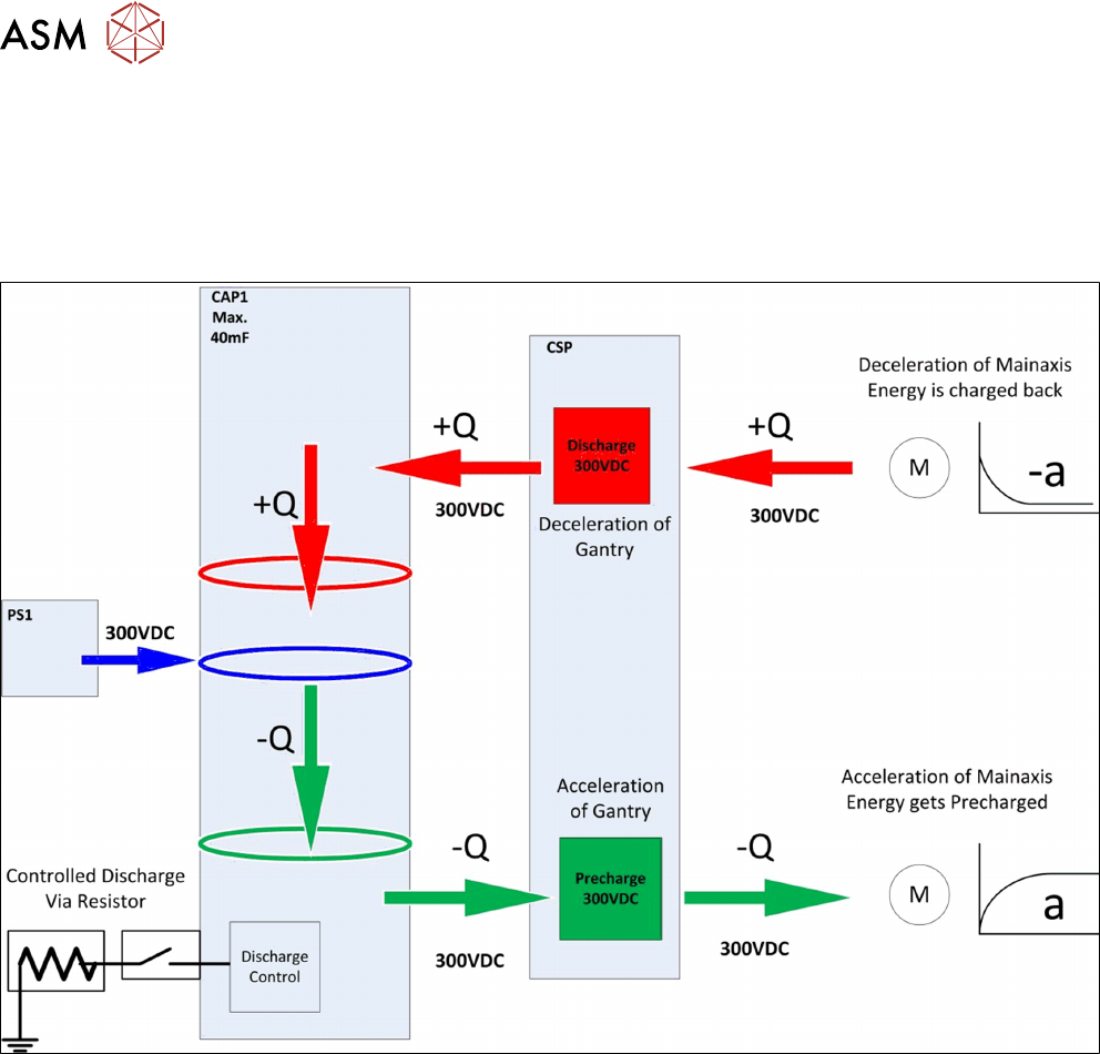
7.4 CAP Function Description
If energy is needed to accelerate the axes (gantry jump), energy is taken from the capacitor battery
(CAP) (pre-charge 300VDC/ -Q)
During braking, the braking energy is fed back by the motors and recharged into the backup battery
(+Q), in a controlled state via the discharge control (discharge 300VDC).
7 Power Supply
7.5 Overview of Fuse board FD:A1
Technical Training FSE SIPLACE TX-Series 01/2018 97
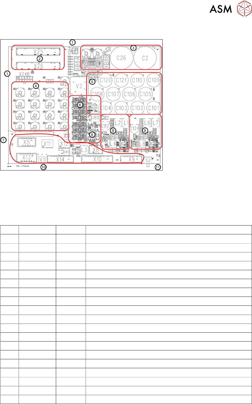
7.5 Overview of Fuse board FD:A1
1. Connector to CSB unit 5. 42V head buffer caps 9. Head Boost converter in-
put 42VDC output
25,5VDC
2. Low voltage input 6. Diagnostic unit
3. Buffer capacitor ,160VDC 7. Output voltages connectors 10. PE connection
4. Low voltage fusing array* 8. Diagnostic data connector 11. Box PC voltage switch
*Fuse types: FUSEHD PCB (5X20MM Vertical)
F1 24 V DC 6.3A MGCU1
F2 24V DC 6.3A MGCU2
F3 24 V DC 6.3A Service
F4 24 V DC 6.3A Distributor Power Fail
F5 24 V DC 6.3A IBASE PC
F6 24 V DC 6.3A Option 3D co-planarity PC
F7 24 V DC 6.3A Conveyor
F8 24 V DC 6.3A Gantry 1
F9 24 V DC 6.3A Gantry 2
F10 24 V DC 0.5A Internal – power fail (internal CSB)
F11 24 V DC 6.3A SSK_Ready
F12 24 V DC 6.3A Safety supply CSB
F13 24 V DC 3A SMD Internal fuse 24V diagnosis replace PCB if defect
F14 42 V DC 6.3A Gantry cable 1 HCU 25,5V converted from 42V
F15 42 V DC 6.3A Gantry cable 2 HCU 25,5V converted from 42V
F16 42 V DC 10A Conveyor drives
F19 160 V DC 6.3A Head axes gantry 1
F20 160 V DC 6.3A Head axes gantry 2
F22 28 V DC 6.3A FCU1
F23 28 V DC 6.3A FCU2
7 Power Supply
7.6 Function Description of Individual Assemblies SMPS TX
98 Technical Training FSE SIPLACE TX-Series 01/2018
7.6 Function Description of Individual Assemblies SMPS TX
7.6.1 Main switch
The main switch is combined with a motor protection switch with combined trip block.
It is approved as a mains breaker device, main switch and protective switch.
The trigger current for the protective switch does not need to be set, however depending on usage
there are 2 different types of motor switch.
●
Standard: Main circuit breaker 3~380-415V: 03125553-(6.3A)
●
Low voltage countries: Main circuit breaker: 3RV27 3 pole 03138992-(12,5A, UL489)
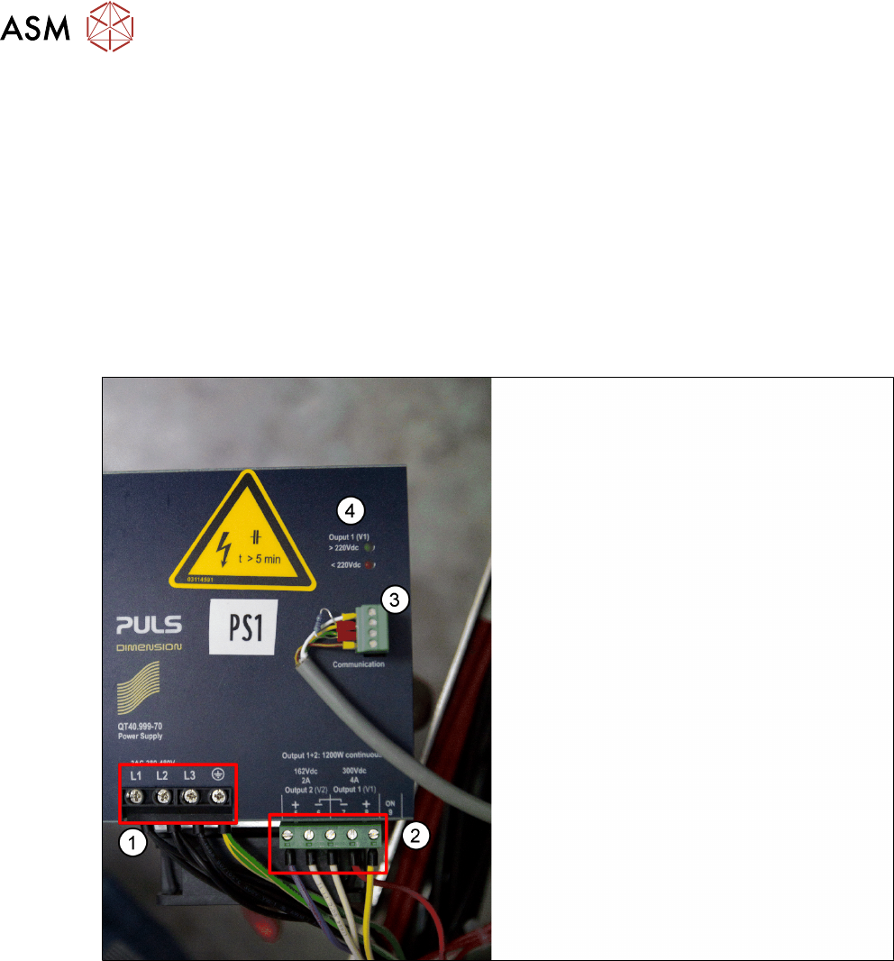
7.6.2 Power Pack PS1-(330 VDC/ 160 VDC)
1. Input Connection 3 phase AC
2. Output 300 VDC/ 160 VDC
3. Diagnosis connector
4. LED for displaying residual voltage
●
The 300VDC voltage is used for the main axis drives. Due to the high current peaks, this
voltage needs to be buffered at the output end.
●
The buffering of the 300VDC voltage is realized with the CAP1 backup battery.
●
A pre/discharge control function on the pre/discharge board A2 is used for controlled energy
release (during acceleration) and energy absorption (during braking) by the backup battery for
the main axes.
●
The 160VDC voltage is used for the head axes. Once again, the high current peaks require
backup storage at the output end.
●
The backup storage of the 160VDC voltage takes place on the pre/discharge board -A2 with
the help of capacitors.