00198171-02_Technical_Training_FSE_TX-Series_EN.pdf - 第66页
6 Conveyor System 6.3 Conveyor Functionality 66 Technical Training FSE SIPLACE TX-Series 01/2018 Board clamping unit The distance between the top of the PCB board and the placement head is always the same for each board,…
6 Conveyor System
6.3 Conveyor Functionality
Technical Training FSE SIPLACE TX-Series 01/2018 65
For full specification details see the User Manual delivered with your machine.
Extract conveyor specification for TX micron
Dual conveyor flexible 20µm /25µm (L X W) 50 mm x 55 mm to 375mm x 260mm
Dual conveyor flexible 15µm (L X W) 50 mm x 55 mm to 250mm x 100mm
Dual conveyor single lane mode 20µm /25µm (L X W) 50 mm x 55 mm to 375mm x 460mm
Standard PCB thickness 0.3 mm to 4.5mm
Maximum PCB weight 2 kg
Clearance below PCB 25 mm
Maximum PCB warpage 2.5 mm
6.3 Conveyor Functionality
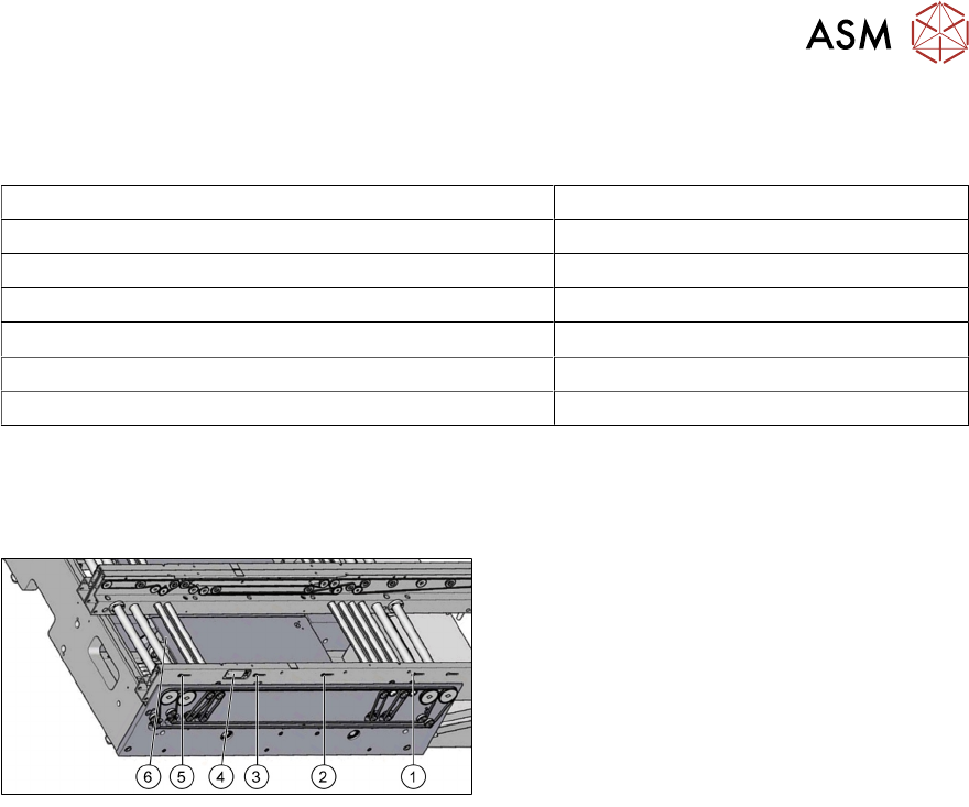
6.3.1 TX Board monitoring and clamping
1. Input section light barrier sensor
2. Second light barrier sensor in PA (option)
3. PA light barrier sensor
4. Laser sensor
5. Output section light barrier sensor
6. Amplifier for light barrier sensor
Board recognition
●
Board recognition is monitored and controlled by fiber optic sensors consisting of a control
unit with transmitter and receiver.
●
Each lane has 3 sets of fiber optic sensors in the Input, PA and Output sections.
●
Each lane has one laser beam sensor in PA.
●
Additional fiber optic sensors for second board stop in PA as option.
Board stopping in placement area
●
When the PCB reaches the placement area, the PCB is detected by an interruption to the light
beam and the speed of the conveyor belt is reduced.
●
About 100ms later, a laser beam recognizes the front edge of the slowly approaching board
and the board will be stopped.
Only for machines with vacuum tooling:
●
When the PCB reaches the placement area, the PCB is detected by an interruption to the light
beam on the vacuum tooling.
●
The conveyor belt changes its direction and the PCB is driven backwards and stopped, when
the PCB reaches the in the station SW defined position (value "Offset PCB sensor back-
wards").
●
Afterwards the lifting table (plate) raised and the vacuum is switched on. When the vacuum
value is reached, the placement process can be started.
Board clamping
●
When the board is stopped, the lifting table (plate) is raised by the lifting motor and clamps the
board.
●
Clamping status is checked using the current and encoder system of the conveyor belt motor.
This function is done by the transport control boards.
●
The PCB will be clamped from the bottom side against a fixed edge on the conveyor system.
6 Conveyor System
6.3 Conveyor Functionality
66 Technical Training FSE SIPLACE TX-Series 01/2018
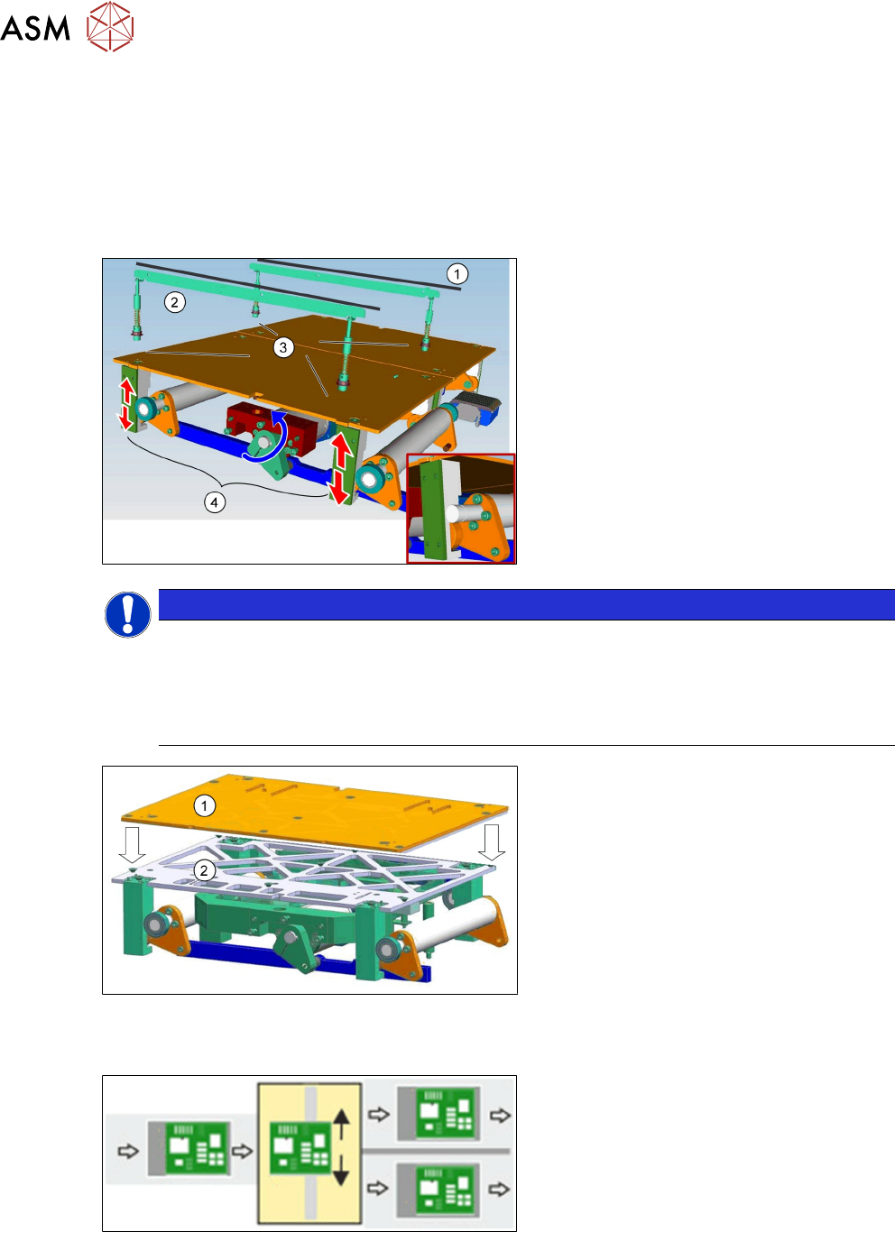
Board clamping unit
The distance between the top of the PCB board and the placement head is always the same for
each board, regardless of the board thickness. This has the following advantages.
●
The placement rate is not dependent on the PCB board thickness.
●
Fiducial recognition is optimized. The consistent space between the board upper edge and
the PCB camera means that the PCB camera is always focused on the upper side of the
board.
1. Conveyor rail
2. Clamping rail
3. Contact points
4. Lifting motor and mechanical device
NOTICE
TX micron 15 µm
In TX micron 15µm machines a lifting table stability reinforcer is installed to ensure a stable
position of the vacuum tooling.
Special feature:
Each vacuum tooling requires a lifting table limit that matches to the PCB thickness.
1.
2.
Lifting table plate
Lifting table stability reinforcer
Shuttle functionality
Single conveyor = > Dual conveyor
Usually, the following right and then left con-
veyor lane are used in alternation. However,
if a conveyor lane is blocked, the other lane
can also be used several times in succes-
sion.
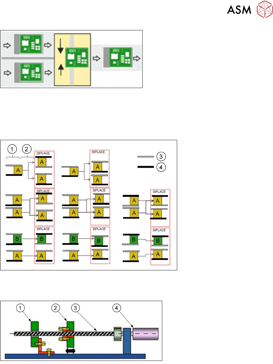
Dual conveyor = > Single conveyor
6 Conveyor System
6.3 Conveyor Functionality
Technical Training FSE SIPLACE TX-Series 01/2018 67
Usually, pickup is from the right and then the
left conveyor lane of the previous machine,
in alternation. However, if there is a problem
at one lane or if there is no board available,
pickup can also be from the other lane sev-
eral times in succession. Precondition: the
same product must be produced on both
lanes.
Shuttle modes
●
Same PCB “A” in both lanes 1 and 2 machine runs in i=placement mode or asynchronous
mode.
●
Two different PCBs “A” and “B” in lane 1 “A” and lane 2 “B” machine runs in i-placement mode
or asynchronous mode.
1. Predecessor
2. Shuttle
3. Moveable rail
4. Fixed rail
For detailed information refer to the shuttle user manual.
6.3.2 Width adjustment
1. Fixed conveyor side
2. Flexible conveyor side
3. Ball screw
4. Motor with belt system
During normal production the width adjustment is set automatically upon product change by
SIPLACE Pro. Manual width adjustment is possible by means of the station software.
The width adjustment is performed with a stepping motor and two ball screws. In a dual conveyor,
different widths are possible for the two conveyor lanes.
During reference run, the conveyor rails edges will be recognized by PCB camera.
Conveyor width is measured by counting system of the motor, if the conveyor width is adjusted
manually with the machine turned off, it may happen that the actual width and the width set in the
station software no longer match and the conveyor width will have to be set.
This can be done using the "find fiducial position" in the station software.