00198171-02_Technical_Training_FSE_TX-Series_EN.pdf - 第52页
5 Component Supply 5.3 Feeder Control Unit (FCU) 52 Technical Training FSE SIPLACE TX-Series 01/2018 Docking ● The docking process can only be performed when the machine is on, compressed air is sup- plied to the machine…
5 Component Supply
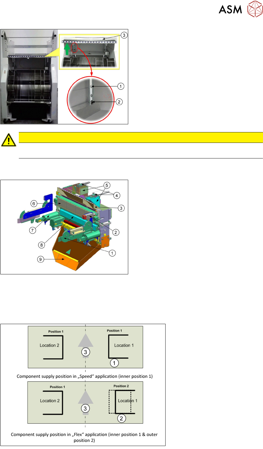
5.2 Docking Station and COT Insert
Technical Training FSE SIPLACE TX-Series 01/2018 51
1. Drilling Hole
2. Cotter Pin
3. Table plate
CAUTION
The COT height should match the machine transport height as incorrect settings can lead
to damage when inserting or removing COT.
5.2 Docking Station and COT Insert
1. Docking claws (on the machine frame)
2. Safety switch
3. Empty tape duct
4. Nozzle station
5. Reject bin
6. FCU
7. Cylinder for claw
8. Feeder unlock device
9. Waste tape chute
●
The COT position is configured as "Speed application" for TX2i or "Flex application" for TX1
and TX2.
●
"Speed application" both location COT at inner position.
●
"Flex application" location 2 at inner position and location 1 at outer position.
●
Only location 1 is possible for the outer position.
1. Inner position
2. Outer position
3. Transport direction
5 Component Supply
5.3 Feeder Control Unit (FCU)
52 Technical Training FSE SIPLACE TX-Series 01/2018
Docking
●
The docking process can only be performed when the machine is on, compressed air is sup-
plied to the machine and the safety covers are closed.
●
To dock the changeover table, push the table as far as possible up to the feed device and
press the button on the machine.
●
On the left and right from the empty tape duct are two centering pins to center the COT for the
final correct pick up position.
●
The feeder contact plate is raised by two pneumatic cylinders and cam disks while, at the
same time, the entire changeover table is pulled into the machine.
Undocking
●
To undock, make sure the compressed air is switched on and control system off and then
press the button on the machine frame.
●
The changeover table is released by the feed device and is pushed out and lowered by two
additional pneumatic cylinders fixed to the left and right of the empty tape duct.
●
The COT will be automatically disconnected from the machine.
●
When the machine is switched off or there is no compressed air supply, the changeover table
can be easily pulled out of the machine by taking hold of the handles.
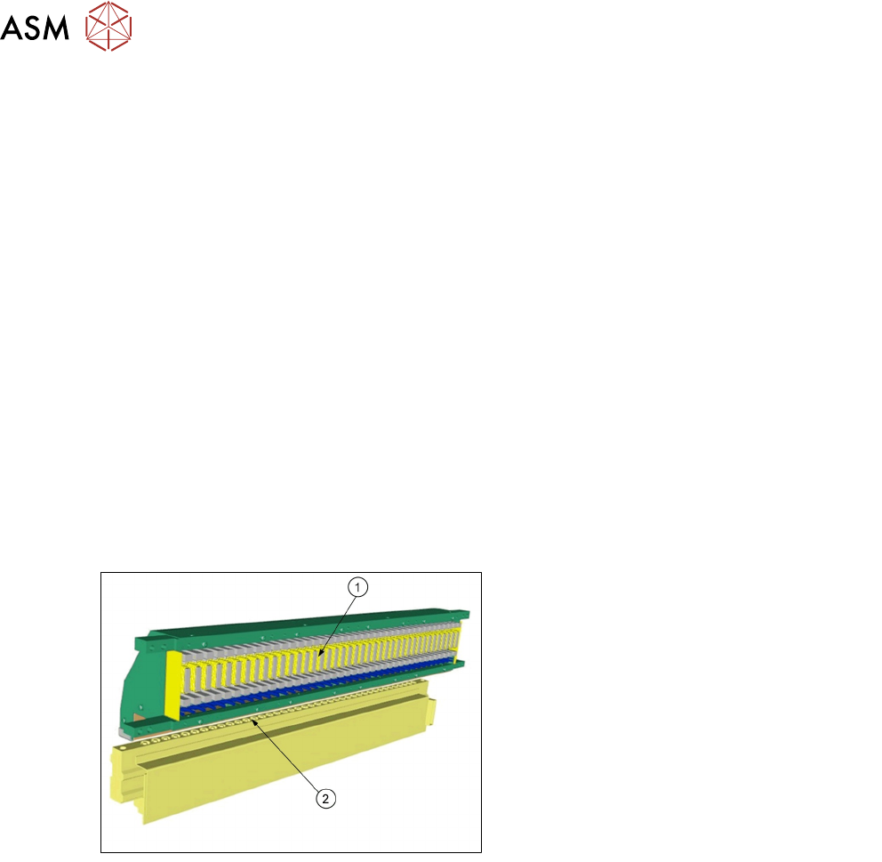
5.3 Feeder Control Unit (FCU)
1. FCU (Feeder Control Unit)
2. Feeder unlock device
●
The FCU is supplied with 28V from the
PULS power supply, all the other internal
voltages (e.g. 24V) are produced intern-
ally.
●
All important voltages are monitored by the
processor. In case of a violation of pre-
defined limits the complete module is shut
down!
The FCU has the following functionality:
●
Triggering of X-feeders and the triggering of the feeder unlock device.
●
Docking unit control.
●
Safety loop and safety message.
●
Triggering of the tape cutter.
●
Triggering of nozzle changers and triggering of the nozzle station (blowing clear)
●
Monitoring of the sensors for the reject bins.
5 Component Supply
5.4 Tape Cutter
Technical Training FSE SIPLACE TX-Series 01/2018 53
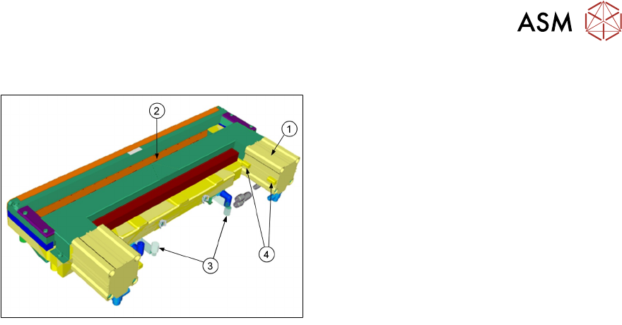
5.4 Tape Cutter
1. Pneumatic cylinder
2. Slot for empty tape
3. Magnetic valves
4. Proximity switch
On both sides of the tape cutter are pneumatic cylinders which activate the blade by alternating
movements. Two solenoid valves (24V / 5.1 bar) controlled by FCU.
The tape cutter is activated when the gantry moves to the first placement position, alternating one
of the cylinders start to front position.
●
Once the first cylinder reaches the front position, the second cylinder is started.
●
Both cylinders are withdrawn at the same time.
●
The cutter will be actuated once after each placement cycle of relevant placement head.
The tape cutter can be removed in about 15 minutes for service purposes. The throttle timings
need to be set. For detailed information about dismantling and settings refer to the service manual.