00198171-02_Technical_Training_FSE_TX-Series_EN.pdf - 第69页
6 Conveyor System 6.3 Conveyor Functionality Technical Training FSE SIPLACE TX-Series 01/2018 69 6.3.4 PCB convoy mode The TX is able to handle up to two PCBs in the placement area to reduce transport time. Pre-condition…
6 Conveyor System
6.3 Conveyor Functionality
68 Technical Training FSE SIPLACE TX-Series 01/2018
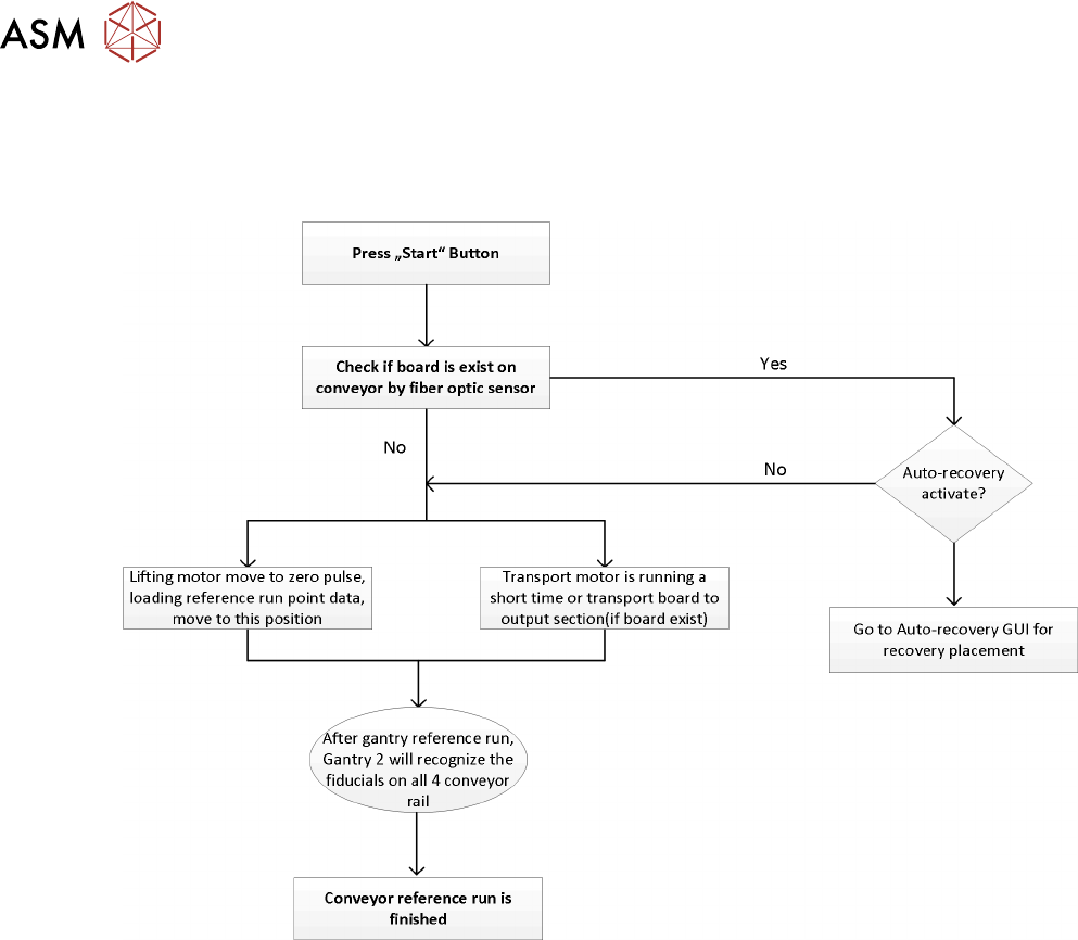
6.3.3 Reference run
During the machine reference run the conveyor system is initialized. This is done after the gantry
reference run is completed. The light barrier and laser light sensitivity is measured and recorded for
use during PCB recognition.
During the reference run the software checks if the rail positions have been changed and issues an
estimated position for each rail. After that the board camera drives to each of the 4 fiducials on the
conveyor rails to determine the exact position and the exact conveyor width.
6 Conveyor System
6.3 Conveyor Functionality
Technical Training FSE SIPLACE TX-Series 01/2018 69
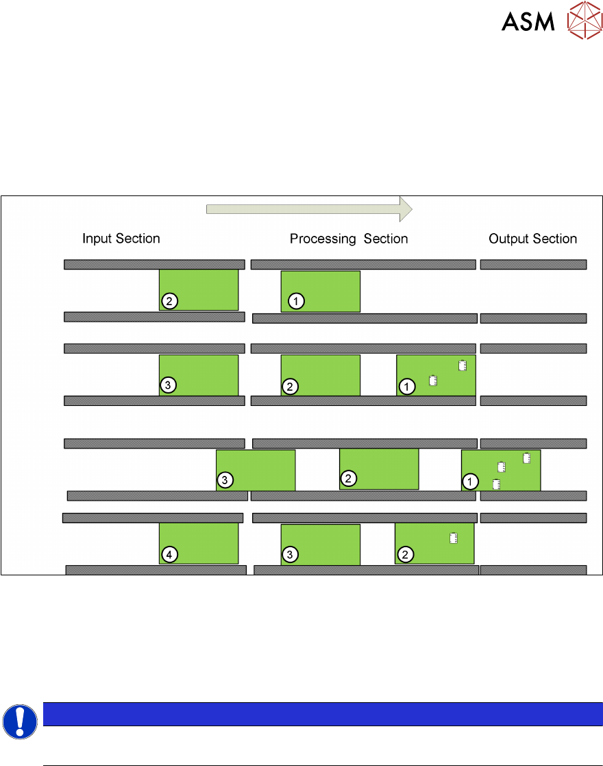
6.3.4 PCB convoy mode
The TX is able to handle up to two PCBs in the placement area to reduce transport time.
Pre-condition:
●
Mode is enabled
●
PCB length is less than 175mm
●
Buffer zone light sensor is installed
A second PCB (PCB 2) is buffered in the processing area. Only PCB 1 will be processed and popu-
lated with components.
When PCB 1 leaves the processing area PCB 2 moves to the stopper and will be processed, at the
same time PCB 3 will move into the buffer zone in the processing area.
The Convoy mode is enabled by default but can be disabled under Service – Conveyor configura-
tion – Lane x – Parameters.
NOTICE
Vacuum tooling
PCB convoy mode is not possible when using vacuum tooling.
6 Conveyor System
6.4 Overview Conveyor Electrical System
70 Technical Training FSE SIPLACE TX-Series 01/2018
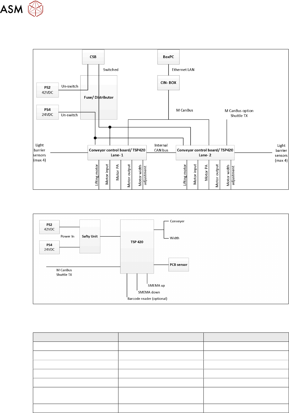
6.4 Overview Conveyor Electrical System
SIPLACE Shuttle
The SIPLACE Shuttle extension has two configurations, namely the upstream and downstream,
wiring connections and jumpers setting are stated below.
For more detailed information refer to the circuit diagram.
Upstream configurations Downstream configuration
Power connection to TX -X15.S1 -X15.S2
CAN bus connection to TX CAN3.EXT CAN3.EXT
Power connection to TX X50 X50
CAN bus connection to shuttle X52 X52
SMEMA connection to TX -XL1 and XL2 upstream -XL1 and XL2 downstream
SMEMA connection to shuttle -XL1-DS and XL2-DS (Down-
stream)
-XL1-US and XL2-US
(Upstream)
TSP 420 jumper setting JP1 pin 1 and 2 is shorted JP1 pin 1 and 2 is shorted
For special configurations where two SIPLACE Shuttle extensions are linked to a single SIPLACE
TXmachine, the CAN cable and TSP 420 jumper setting will be configured as per below.