00198171-02_Technical_Training_FSE_TX-Series_EN.pdf - 第84页
6 Conveyor System Room for Your Sketches and Notes 84 Technical Training FSE SIPLACE TX-Series 01/2018

6 Conveyor System
Room for Your Sketches and Notes
Technical Training FSE SIPLACE TX-Series 01/2018 83
Room for Your Sketches and Notes

6 Conveyor System
Room for Your Sketches and Notes
84 Technical Training FSE SIPLACE TX-Series 01/2018
7 Power Supply
7.1 Overview of the Switched Mode Power Supply SMPS
Technical Training FSE SIPLACE TX-Series 01/2018 85
7 Power Supply
7.1 Overview of the Switched Mode Power Supply SMPS
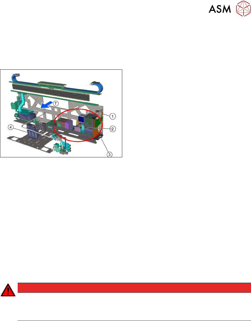
T - Transport direction
1. Main machine switch
2. Power Supply unit located behind the
panel below mains switch accessible on a
pullout rack
3. Handle for pull out rack
4. Transformer for use in low voltage coun-
tries access from behind COT location 2
The mains supply cable is connected to the connection terminals in sector 1 at the output end.
The power supply for TX consists of one assembly, located behind the cover at location 2.
The Power Supply is known as SMPS (Switched Mode Power Supply).
All voltages needed for machine operation are generated by SMPS.
Power supply SMPS components
●
Generation of all supply voltages needed (300V,160V, 42V, 28V, 24V).
●
Distribution and fusing of output voltages.
●
Diagnostic interface for fuse state and power converter diagnosis.
●
Safety control of link voltages (42V, 160V and 300VDC) and signal (24V-S and Power Enable
signal).
●
DC voltage backup for main axes (CAP = capacitor battery buffer), IO and signal distribution.
●
Modular gantry drives servo/control units (MGCU).
●
Machine cable harness interface.
DANGER
The unit contains energy storage components with timed discharge, be careful when work
has to be done at 300V and 160V DC parts of the unit. Wait 5 min before commencing any
work on the SMPS connection or disconnection of units is allowed only in discharged state.
Measure the voltages before commencing any work on SMPS.