00193437-03_AI_PowerSupplyConversion_DE+EN.pdf - 第176页
3 Converting the power supply on HF machines A ssembly Instructions, Converting the Power Supply 3.6 Converting the power supply from 3 x 208 VAC to 3 x 400 VAC 12/2013 Edition 174 3.6.5 Configuring the inrush current li…
Assembly Instructions, Converting the Power Supply 3 Converting the power supply on HF machines
12/2013 Edition 3.6 Converting the power supply from 3 x 208 VAC to 3 x 400 VAC
173
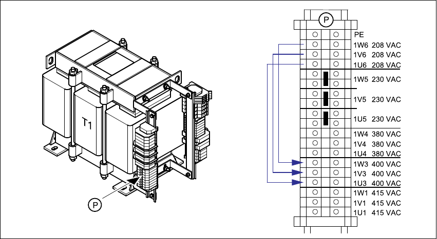
3.6.4 Converting the three-phase transformer T1 from 3 x 208 VAC to 3 x 400 VAC
Connect the cable from
terminal 1W6 to terminal 1W3
terminal 1V6 to terminal 1V3 and
terminal 1U6 to terminal 1U3.
Fig. 3 - 21 Primary terminals for transformer T1
3 Converting the power supply on HF machines Assembly Instructions, Converting the Power Supply
3.6 Converting the power supply from 3 x 208 VAC to 3 x 400 VAC 12/2013 Edition
174
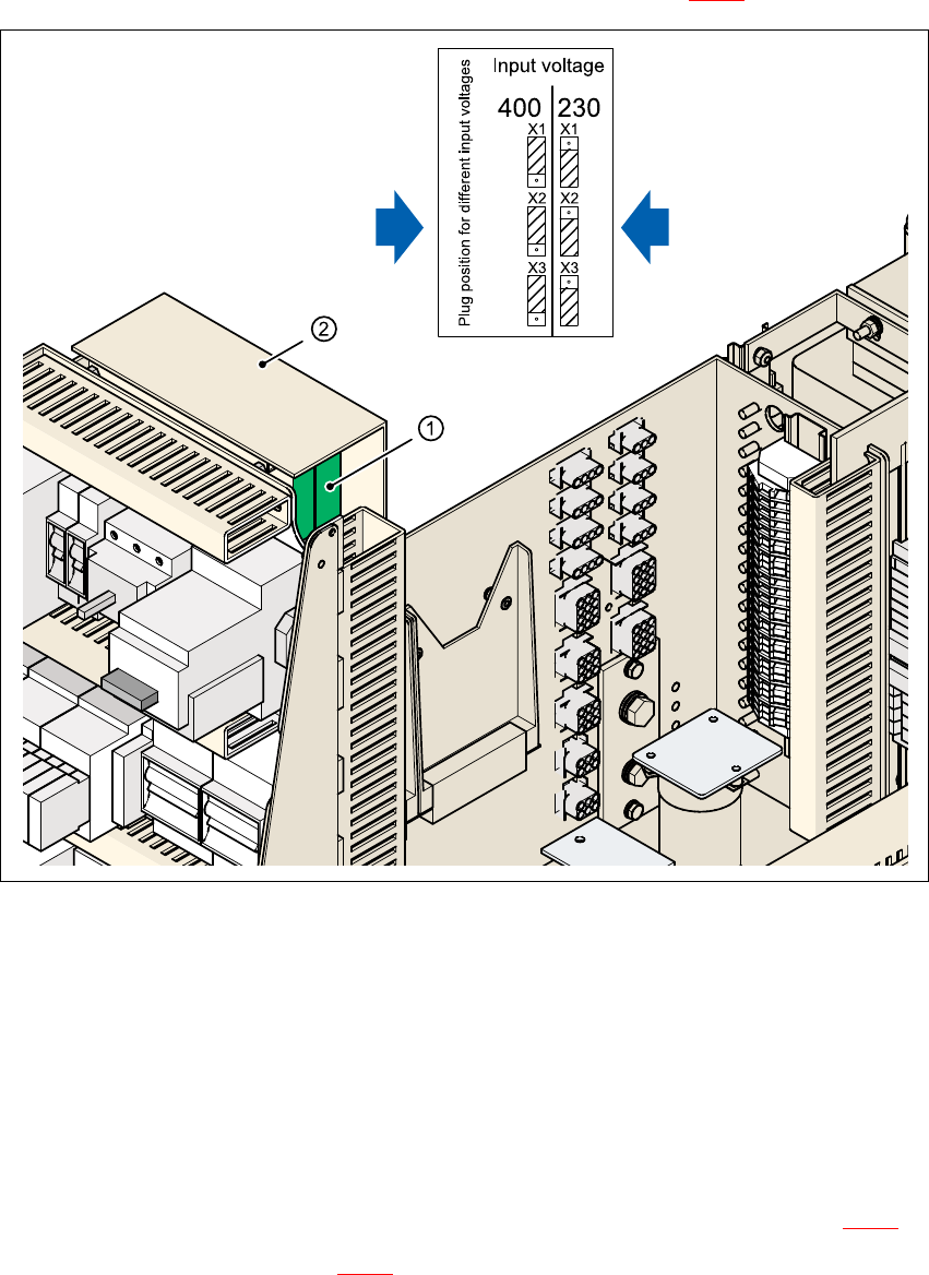
3.6.5 Configuring the inrush current limiter board
The inrush current limitation must be configured in relation to the supply voltage. This is done us-
ing plug-in jumpers on the inrush current limitation board (item 1 in Fig. 3 - 22
).
3
Fig. 3 - 22 Configuring the EST inrush current limiter board
3
(1) Inrush current limitation board
(2) Cover
X1, X2, X3 Connectors for configuring the inrush current limitation
Remove the cover.
Remove the jumper plugs from connectors X1, X2 and X3.
Plug in the jumper plugs one position higher on connectors X1, X2 and X3 (see Fig. 3 - 22).
Fit the cover (see item 2 in Fig. 3 - 22).
3 x 380 VAC
3 x 400 VAC
3 x 415 VAC
3 x 208 VAC
3 x 230 VAC

Assembly Instructions, Converting the Power Supply 3 Converting the power supply on HF machines
12/2013 Edition 3.7 HF circuit diagrams
175
3.6.6 Installing the power supply unit
Carefully push the power supply unit into the housing until it reaches the stop.
Use the M8 hexagon socket-head screw to secure the unit at the bottom.
Check that the yellow-green PE wire is connected to the cover.
Attach the holding cord to the eye in the cover.
Attach the cover.
PLEASE NOTE: 3
Make sure that the actuating shaft of the main switch slides easily into the opening in the ro-
tary button. 3
Use the machine key to lock the cover.
3.6.7 Carry out the safety check to DIN EN 60 204
When the conversion is complete, carry out a safety check to DIN EN 60 204.
Follow the procedure described in section 2, page 146 onwards.
3.7 HF circuit diagrams
– Conversion kit, USA (208 VAC), SIPLACE HF,
drawing no. 00119605-020101LD4, 2 sheets (see page 176
and 177)
– Conversion kit, international, SIPLACE HF,
drawing no. 00354626-060301LD4, 2 sheets (see page 178
and 179)