00193437-03_AI_PowerSupplyConversion_DE+EN.pdf - 第191页
Assembly Instructions, Converting the Power S upp ly 4 Converting the power supply o n the MTC2 12/2013 Edition 4.5 Converting the power supply from 3 x 208 VAC to 3 x 400 VAC 189 4.5.2 Checking the protective wire conne…
4 Converting the power supply on the MTC2 Assembly Instructions, Converting the Power Supply
4.5 Converting the power supply from 3 x 208 VAC to 3 x 400 VAC 12/2013 Edition
188
4
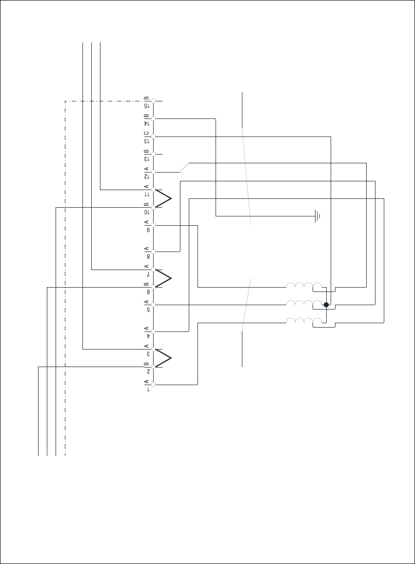
Fig. 4 - 6 MTC2 - terminal panel X01, circuit diagram 3 x 400 VAC
1V1
1 2 3
2U1
2V1
2W1
4x2.5mm² CSA
1W1
1U1
3.7 kVA /50-60Hz
Oilflex 190
-W002
Transformer T01
3 x 208 VAC / 3 x 400 VAC
3 x 400 VAC / 230 VAC
L1
L2
50Hz / 60 Hz
L3
PE
Terminal panel X01
5x2.5mm² CSA
1 2 3 4
Oilflex 190
-W003
PE
L3.1
L1.1
L2.1
C
A A
JMP
JMP: 3 x 400 VAC
JMP JMP
N

Assembly Instructions, Converting the Power Supply 4 Converting the power supply on the MTC2
12/2013 Edition 4.5 Converting the power supply from 3 x 208 VAC to 3 x 400 VAC
189
4.5.2 Checking the protective wire connections, fitting the covers
Check that the detached protective earth wires have been reconnected correctly.
Fit the cover.
4.5.3 Carry out the safety check to DIN EN 60 204
When the conversion is complete, carry out a safety check to DIN EN 60 204.
Follow the procedure described in section 2, page 146 onwards.
4

5 Converting the power supply on S-27 HM machines/ and on component trolleys Assembly Instructions, Converting the Power Supply
5.1 Versions of the affected power supply units 12/2013 Edition
190
5 Converting the power supply on S-27 HM
machines/
and on component trolleys
5.1 Versions of the affected power supply units
This section describes how to convert the power supply units for the SIPLACE S-27 HM place-
ment machine and the component trolley.This will allow the power supply units to be adapted to
the supply networks in individual countries. 5
These instructions apply to machines with the following power supply unit releases: 5
– S-27 HM placement system with power supply 00336812 from function status 04
– Component trolley 00116226 from function status 01
5.2 Tools and equipment
– Set of DIN 911 Allen keys
– Set of slotted-head screwdrivers
– Multimeter
5.3 Circuit diagrams
– SIPLACE S-27 HM circuit diagram, 3 x 400 VAC power socket, 3 x 208 VAC power socket,
drawing no. 00336812-040301LD3, 1 sheet (see Fig. 5 - 13
, page 211)
– Circuit diagram for the component trolley transformer, old version (see Fig. 5 - 14
, page 212)
drawing no. 00301239-040301LD4
– Circuit diagram for the component trolley transformer, new version (see Fig. 5 - 15
, page 213)
drawing no. 00301239-060101LD4
5.4 Parts
120/208 V conversion kit for Siplace S-27 HM, item no. 00117185-01, consisting of: 5
– 5 x 20, T 6.3 A, fusible element, 10 x (for 115 VAC component trolley)
item no. 00806005-01
– 5 x 20, T 3.15 A, fusible element, 10 x (for 230 VAC component trolley)
item no. 00304938-01
– Teddy socket guard, 6310 series, white (for service socket)