00193437-03_AI_PowerSupplyConversion_DE+EN.pdf - 第204页
5 Converting the power supply on S-27 HM machines/ and on component trolleys Assembly Instructions, Converting the Power Supply 5.8 Converting the S-27 HM from 3 x 400 VAC to 3 x 208 VAC 12/2013 Edition 202 5.8 Convertin…

Assembly Instructions, Converting the Power Supply 5 Converting the power supply on S-27 HM machines/ and on component trolleys
12/2013 Edition 5.7 Converting the component trolley from 230 VAC to 120 VAC
201
5.7.2 Replacing the fuse
There are two versions of the main power supply for the component trolley: 5
Replacing the fuse F1 on the old power supply 5
Here, the fuse is located on the primary side of transformer T1. The fuse F1 must be replaced (see
circuit diagram 00301239-040301LD4, page 212
) 5
Replace the fuse in the fuse holder in the cover panel:
old rating: 3.15 A T
new rating: 6.3 A T
Replace the adhesive label specifying 3.15 A with the 6.3 A label from the conversion kit.
Replace the cover panel over the transformer and tighten the four hexagon socket-head
screws.
New power supply 5
Here there are two fuses on the secondary side of transformer T1. The fuses do not have to be
replaced (see circuit diagram 00301239-060101LD4, page 213
) 5
Replace the cover panel over the transformer and tighten the four hexagon socket-head
screws.
5.7.3 Checking the protective earth wire connections
Check that the detached protective earth wires have been reconnected correctly.
5.7.4 Carry out the safety check to DIN EN 60 204
When the conversion is complete, carry out a safety check to DIN EN 60 204.
Follow the procedure described in section 2, page 146 onwards.
5 Converting the power supply on S-27 HM machines/ and on component trolleys Assembly Instructions, Converting the Power Supply
5.8 Converting the S-27 HM from 3 x 400 VAC to 3 x 208 VAC 12/2013 Edition
202
5.8 Converting the S-27 HM from 3 x 400 VAC to 3 x 208 VAC
PLEASE NOTE: 5
Dock out the two component trolleys before switching off the machine. 5
RISK OF DEATH 5
Disconnect the machine correctly as described in section 1, page 145.
Disconnect the machine from the main power supply.
Take suitable action to ensure that the machine cannot be connected to the power supply dur-
ing the conversion work.
Put up warning signs to indicate that work is being carried out on the electrical system.
Assembly Instructions, Converting the Power Supply 5 Converting the power supply on S-27 HM machines/ and on component trolleys
12/2013 Edition 5.8 Converting the S-27 HM from 3 x 400 VAC to 3 x 208 VAC
203
5.8.1 Removing the power supply unit
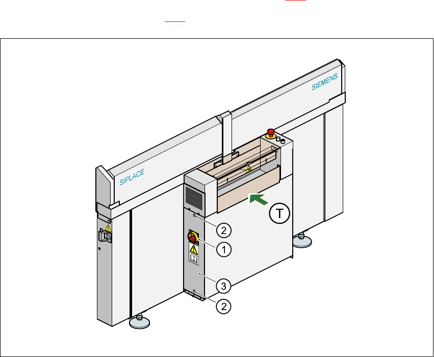
Loosen the two hexagon socket head screws (item 2 in Fig. 5 - 8).
Remove the cover (item 3 in Fig. 5 - 8).
Fig. 5 - 8 Removing the cover over the power supply unit
(1) Main switch
(2) Hexagon socket head screw, 2x
(3) Cover
(T) PCB transport direction 5
5
Loosen the hexagon socket-head screw at the bottom of the power supply unit.
Take hold of the handle and remove the power supply unit from the housing.
The terminals on transformers T1 and T2 and the inrush current limiter can now be accessed
for rewiring.