00193437-03_AI_PowerSupplyConversion_DE+EN.pdf - 第229页
Assembly Instructions, Converting the Power Supp ly 6 Converting the power supply on the MTC 12/2013 Edition 6.5 Converting the power supply from 3 x 208 VAC to 3 x 400 VAC 227 6.5.2.2 Replacing fuse F1 Replace the fus…
6 Converting the power supply on the MTC Assembly Instructions, Converting the Power Supply
6.5 Converting the power supply from 3 x 208 VAC to 3 x 400 VAC 12/2013 Edition
226
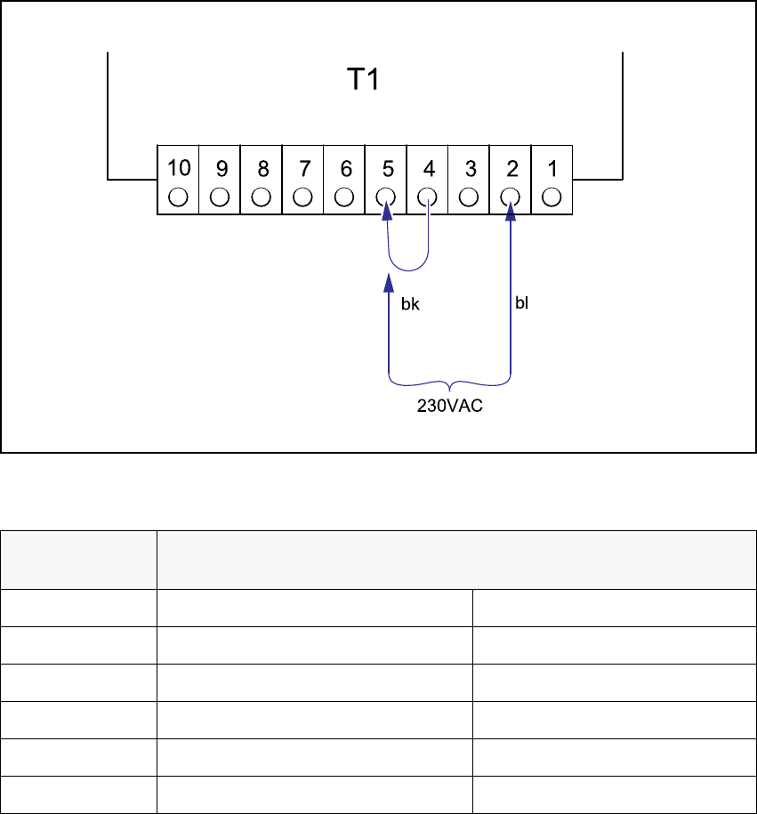
T1 Transformer for the main power supply for communication on the component table 6
Fig. 6 - 10 Changeover table, transformer T1, terminals
6
6
Detach the black wire from terminal 4 and connect to terminal 5.
Voltage
Terminals
Blue wire Black wire
242 VAC 1 5
230 VAC 2 5
219 VAC 3 5
126 VAC 1 4
120 VAC 2 4
114 VAC 3 4
Tab. 6 - 1 Changeover table, supply voltages for transformer T1

Assembly Instructions, Converting the Power Supply 6 Converting the power supply on the MTC
12/2013 Edition 6.5 Converting the power supply from 3 x 208 VAC to 3 x 400 VAC
227
6.5.2.2 Replacing fuse F1
Replace the fuse in the fuse holder in the cover panel:
old rating: 6.3 AT
new rating: 3.15 AT
Replace the adhesive label specifying 6.3 A with the 3.15 A label from the conversion kit.
6.5.3 Checking the protective wire connections, fitting the covers
Check that the detached protective earth wires have been reconnected correctly.
Fit the covers.
6.5.4 Carry out the safety check to DIN EN 60 204
When the conversion is complete, carry out a safety check to DIN EN 60 204.
Follow the procedure described in section 2, page 146 onwards.
6
6
6
6
6

7 Converting the power supply on the HS-60 / D4 / D1/D2 machine Assembly Instructions, Converting the Power Supply
7.1 Tools and equipment 12/2013 Edition
228
7 Converting the power supply on the HS-60 / D4 / D1/
D2 machine
This section describes how to convert the power supply unit on the HS-60 placement machine in
order to adapt it to the supply networks in individual countries.
The motor circuit-breakers only need to be retrofitted on the HS-60 and D4. On the D1/D2 they
only have to be readjusted:
– Motor protection trip block: ZM-16-PKZ2; 00342495-xx
3 x 415 VAC ± 5%; 3 x 400 VAC ± 5%; 3 x 380 VAC ± 5%
– Motor protection trip block: ZM-32-PKZ2, USA option: 00342496-xx
3 x 230 VAC ± 5%; 3 x 208 VAC ± 5%
7.1 Tools and equipment
– Set of DIN 911 Allen keys
– Set of slotted-head screwdrivers
– Multimeter
7.2 Circuit diagrams
– Circuit diagram, 3 x 208 V~ conversion kit for SIPLACE HS-60
drawing no. 00119085-050101LD4, 2 sheets (see page 252
and 253)
– Circuit diagram, SIPLACE HS-60 conversion kit, international,
drawing no. 00119185-050101LD4, 2 sheets (see page 254
and 255)