00193437-03_AI_PowerSupplyConversion_DE+EN.pdf - 第267页
Assembly Instructions, Converting the Power Supp ly 8 Converting the power supply on the HS- XX / Di machine using PKE32/XTU-32 12/2013 Edition 8.5 Converting the power supply from 3 x 400 VAC to 3 x 208 VAC 265 8.5.6 Co…
8 Converting the power supply on the HS-XX / Di machine using PKE32/XTU-32 Assembly Instructions, Converting the Power Supply
8.5 Converting the power supply from 3 x 400 VAC to 3 x 208 VAC 12/2013 Edition
264
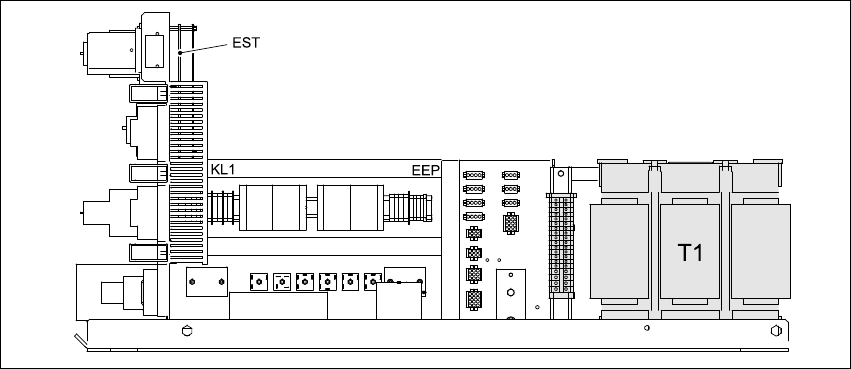
8.5.5 Overview of the parts - power supply unit - side view
Fig. 8 - 4 Overview of the parts - power supply unit - side view
EST Inrush current limiter board TG 31033-01
T1 Three-phase transformer
Assembly Instructions, Converting the Power Supply 8 Converting the power supply on the HS-XX / Di machine using PKE32/XTU-32
12/2013 Edition 8.5 Converting the power supply from 3 x 400 VAC to 3 x 208 VAC
265
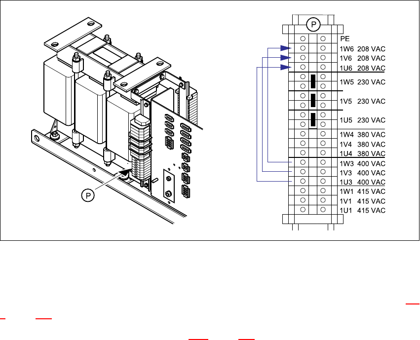
8.5.6 Converting the three-phase transformer T1 from 3 x 400 VAC to 3 x 208 VAC
Reconnect the cables on the primary terminals:
from terminal 1W3 to terminal 1W6
from terminal 1V3 to terminal 1V6
from terminal 1U3 to terminal 1U6
Fig. 8 - 5 Primary terminals for transformer T1
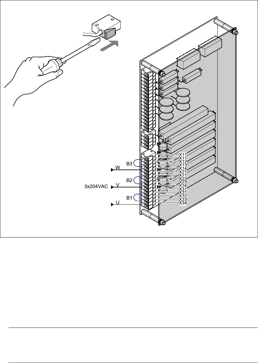
8.5.7 Reconnecting the inrush current limiter board
The inrush current limiter board is located on the back of the front panel (see item EST in Fig. 8 -
4, page 264.
Reconnect the following wires (see Fig. 8 - 6, page 266):
(W) from terminal X13 to terminal X14,
(V) from terminal X23 to terminal X24 and
(U) from terminal X33 to terminal X34.
Move the following jumpers:
B3 from terminal X12 to terminal X13
B2 from terminal X22 to terminal X23 and
B1 from terminal X32 to terminal X33.
8 Converting the power supply on the HS-XX / Di machine using PKE32/XTU-32 Assembly Instructions, Converting the Power Supply
8.5 Converting the power supply from 3 x 400 VAC to 3 x 208 VAC 12/2013 Edition
266
)
Fig. 8 - 6 Reconnecting the EST inrush current limiter board
8.5.8 Installing the power supply unit
Carefully push the power supply unit into the housing until it reaches the stop.
Use the M8 hexagon socket-head screw to secure the unit at the bottom.
Check that the yellow-green PEwire is connected to the door.
Close the door.
PLEASE NOTE: 8
Make sure that the actuating shaft of the main switch slides easily into the opening in the ro-
tary button. 8
Use the machine key to lock the door.