00193437-03_AI_PowerSupplyConversion_DE+EN.pdf - 第177页
Assembly Instructions, Converting the Power S upp ly 3 Converting the power supply on HF machines 12/2013 Edition 3.7 HF circuit diagrams 175 3.6.6 Inst alling the power supply unit Carefully push the power su pply uni…
3 Converting the power supply on HF machines Assembly Instructions, Converting the Power Supply
3.6 Converting the power supply from 3 x 208 VAC to 3 x 400 VAC 12/2013 Edition
174
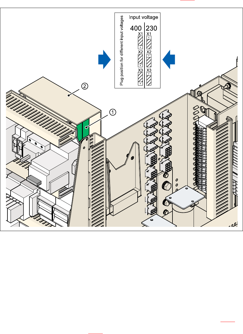
3.6.5 Configuring the inrush current limiter board
The inrush current limitation must be configured in relation to the supply voltage. This is done us-
ing plug-in jumpers on the inrush current limitation board (item 1 in Fig. 3 - 22
).
3
Fig. 3 - 22 Configuring the EST inrush current limiter board
3
(1) Inrush current limitation board
(2) Cover
X1, X2, X3 Connectors for configuring the inrush current limitation
Remove the cover.
Remove the jumper plugs from connectors X1, X2 and X3.
Plug in the jumper plugs one position higher on connectors X1, X2 and X3 (see Fig. 3 - 22).
Fit the cover (see item 2 in Fig. 3 - 22).
3 x 380 VAC
3 x 400 VAC
3 x 415 VAC
3 x 208 VAC
3 x 230 VAC

Assembly Instructions, Converting the Power Supply 3 Converting the power supply on HF machines
12/2013 Edition 3.7 HF circuit diagrams
175
3.6.6 Installing the power supply unit
Carefully push the power supply unit into the housing until it reaches the stop.
Use the M8 hexagon socket-head screw to secure the unit at the bottom.
Check that the yellow-green PE wire is connected to the cover.
Attach the holding cord to the eye in the cover.
Attach the cover.
PLEASE NOTE: 3
Make sure that the actuating shaft of the main switch slides easily into the opening in the ro-
tary button. 3
Use the machine key to lock the cover.
3.6.7 Carry out the safety check to DIN EN 60 204
When the conversion is complete, carry out a safety check to DIN EN 60 204.
Follow the procedure described in section 2, page 146 onwards.
3.7 HF circuit diagrams
– Conversion kit, USA (208 VAC), SIPLACE HF,
drawing no. 00119605-020101LD4, 2 sheets (see page 176
and 177)
– Conversion kit, international, SIPLACE HF,
drawing no. 00354626-060301LD4, 2 sheets (see page 178
and 179)

3 Converting the power supply on HF machines Assembly Instructions, Converting the Power Supply
3.7 HF circuit diagrams 12/2013 Edition
176
3
Fig. 3 - 23 Conversion kit, USA (208 VAC) for SIPLACE HF, item no. 00119605-020101LD4, sheet 1 of 2
USA conversion kit (208V)
00119605-020101LD4
2
16.10.2002
Hoffmann K.
400515 24.04.03US02
Tek400623 24.07.03FS02
SD EA 1 R&D
Date
Author
Check.
Stand.
NameModifiedStatus
Sheet
Sh.
SIEMENS
DEMATIC
Date
Q2
Power switch
Main switch
Q1
L1
L2
L3
T1
T2
T3
L1
L2
L3
T1
T2
T3
L20
F23
3 xT6.3A
F22
F21
1
Inrush current limiter - transformer
L1 (U)
L2 (V)
L3 (W)
N
PE
PE
N
RGP
PE
F1
Line filter
K1.1
K1 main contactor
TransfPrim
SZ1(-)
RGP
MGP
SZ1(+)
6A
6 bn
6 bn
6 bn 6 bn
6 bn
6 bn
Contactor relay block (NC)
Service
socket
X102
X100
Z1
MGP
RGP
Frame
L1
L2
L3
L1
L2
L3
L1'
L2'
L3'
00342496
Motor protection trip block 32 A
Reconnected for the USA
Lock socket with socket guard
00345937
USA main power cable
1
2
3
4
gnye
1
2
3
4
gnye
Rack grounding point
Main grounding point (frame)
SIPLACE HF
Comunicado como segredo empresarial. Reservados todos os direitos.
Confie a titre de secret d'entreprise. Tous droits reserves.
Proprietary data , company confidential . All rights reserved.
Confiado como secrete industrial. Nos reservamos todos los derechos.
Weitergabe sowie Vervielfaeltigung dieser Unterlage, Ver-
wertung und Mitteilung ihres Inhalts nicht gestattet, soweit
nicht ausdruecklich zugestanden. Alle Rechte vorbehalten, ins-
besondere fuer den Fall der Patenterteilung oder GM-Eintragung.