00193437-03_AI_PowerSupplyConversion_DE+EN.pdf - 第235页
Assembly Instructions, Converting the Power Supp ly 7 Conv erting the power supply on the HS-60 / D4 / D1/D2 machine 12/2013 Edition 7.5 Converting the power supply from 3 x 400 VAC to 3 x 208 VAC 233 Fig. 7 - 2 Power su…
7 Converting the power supply on the HS-60 / D4 / D1/D2 machine Assembly Instructions, Converting the Power Supply
7.5 Converting the power supply from 3 x 400 VAC to 3 x 208 VAC 12/2013 Edition
232
7.5.1 Removing the power supply unit
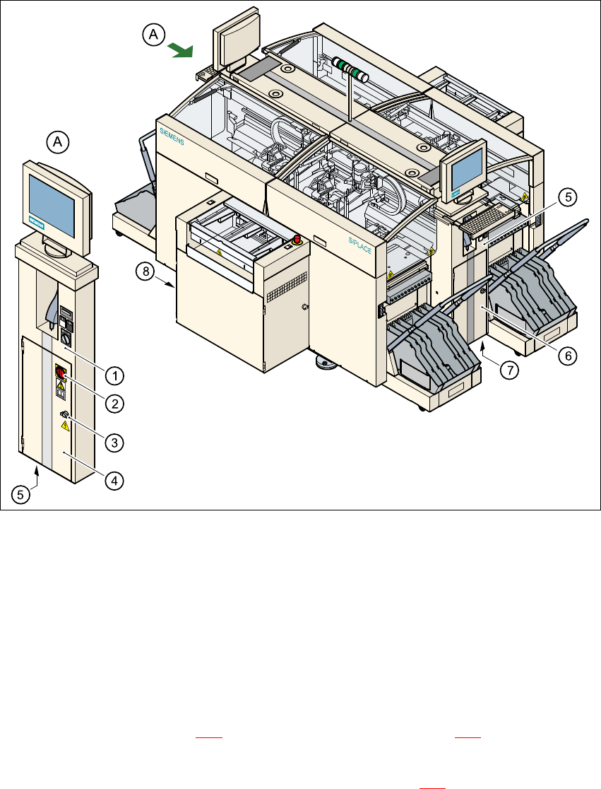
Fig. 7 - 1 Accessing the power supply unit
(1) Operator panel, left-hand side
(2) Main switch
(3) Door lock
(4) Protective doors to power supply unit
(5) Hole for power cable
Open the lock (item 3 in Fig. 7 - 1) on the protective door (item 4 in Fig. 7 - 1 using the machine
key.
Use the Allen key to loosen the M8 locking screw (item M8 in Fig. 7 - 2) on the lower front panel.
Pull the power supply unit out as far as the stop.
Assembly Instructions, Converting the Power Supply 7 Converting the power supply on the HS-60 / D4 / D1/D2 machine
12/2013 Edition 7.5 Converting the power supply from 3 x 400 VAC to 3 x 208 VAC
233
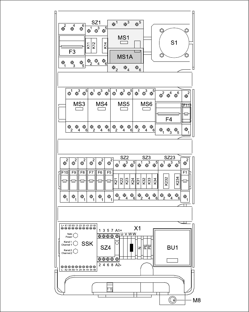
Fig. 7 - 2 Power supply unit front view
MS1 Motor circuit-breaker
MS1A Motor protection trip block
X1 Terminal strip for the main power cable
BU1 Service socket
M8 Locking screw for power supply unit
7 Converting the power supply on the HS-60 / D4 / D1/D2 machine Assembly Instructions, Converting the Power Supply
7.5 Converting the power supply from 3 x 400 VAC to 3 x 208 VAC 12/2013 Edition
234
7.5.2 Replacing the motor protection trip block
The motor circuit-breakers only need to be retrofitted on the HS-60 and D4. On the D1/D2 they
only have to be readjusted.
The ZM-32-PKZ2 motor protection trip block, item number 00342496-01, must be used for 3x208
VAC and 3x230 VAC supply voltages. The position of the motor protection trip block is shown in
Fig. 7 - 2
, item MS1A.
7.5.2.1 Removing the motor protection trip block
7
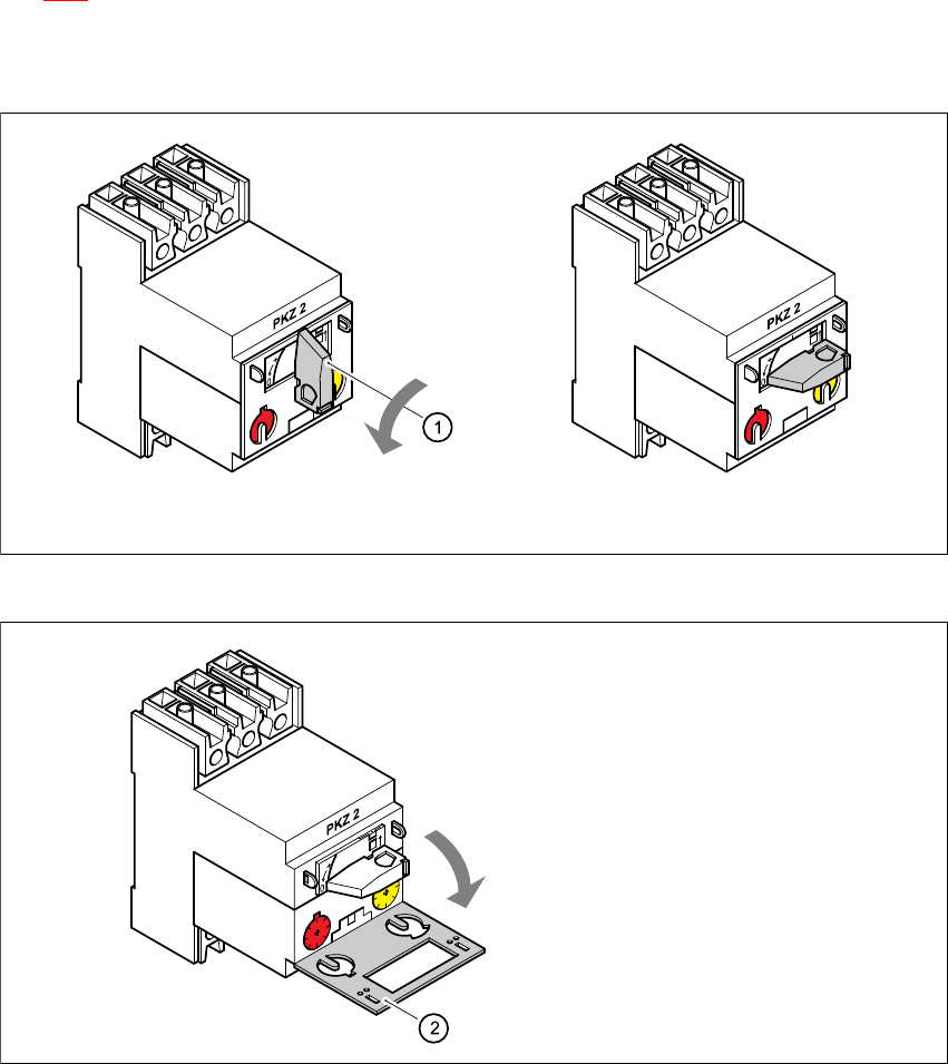
Fig. 7 - 3 Removing the motor protection trip block MS1A
7
Fig. 7 - 4 Lifting the protective flap
Turn the switch (1) counter-clockwise to the "0" position
Lift the
protective flap (2)