00193437-03_AI_PowerSupplyConversion_DE+EN.pdf - 第269页
Assembly Instructions, Converting the Power Supp ly 8 Converting the power supply on the HS- XX / Di machine using PKE32/XTU-32 12/2013 Edition 8.6 Converting the power supply from 3 x 208 VAC to 3 x 400 VAC 267 8.5.9 Ca…
8 Converting the power supply on the HS-XX / Di machine using PKE32/XTU-32 Assembly Instructions, Converting the Power Supply
8.5 Converting the power supply from 3 x 400 VAC to 3 x 208 VAC 12/2013 Edition
266
)
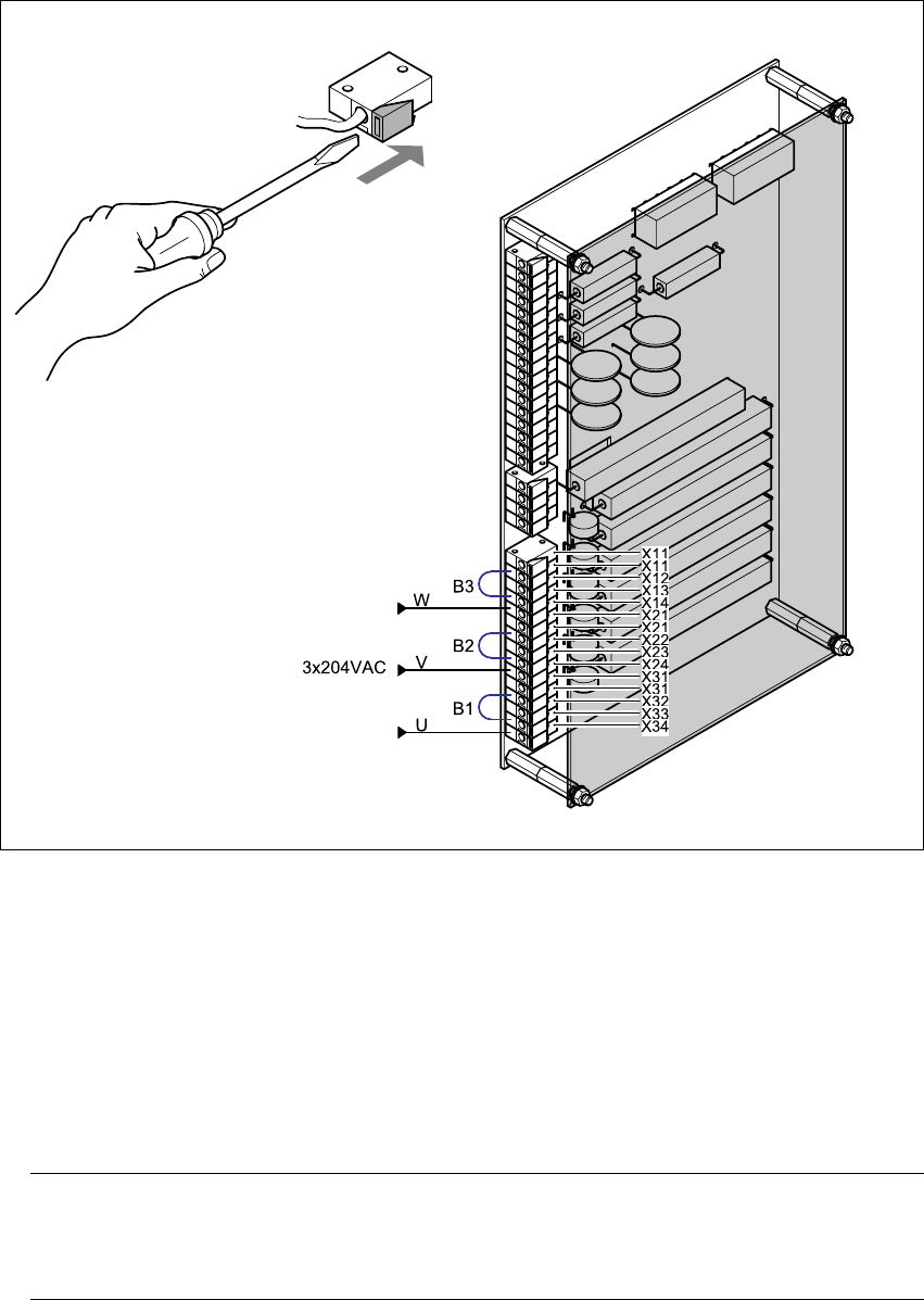
Fig. 8 - 6 Reconnecting the EST inrush current limiter board
8.5.8 Installing the power supply unit
Carefully push the power supply unit into the housing until it reaches the stop.
Use the M8 hexagon socket-head screw to secure the unit at the bottom.
Check that the yellow-green PEwire is connected to the door.
Close the door.
PLEASE NOTE: 8
Make sure that the actuating shaft of the main switch slides easily into the opening in the ro-
tary button. 8
Use the machine key to lock the door.

Assembly Instructions, Converting the Power Supply 8 Converting the power supply on the HS-XX / Di machine using PKE32/XTU-32
12/2013 Edition 8.6 Converting the power supply from 3 x 208 VAC to 3 x 400 VAC
267
8.5.9 Carry out the safety check to DIN EN 60 204
When the conversion is complete, carry out a safety check to DIN EN 60 204.
Follow the procedure described in section 2, page 146 onwards.
8
8.6 Converting the power supply from 3 x 208 VAC to 3 x 400 VAC
RISK OF DEATH 8
Disconnect the machine correctly as described in section 1, page 145.
Disconnect the machine from the main power supply.
Take suitable action to ensure that the machine cannot be connected to the power supply dur-
ing the conversion work.
Put up warning signs to indicate that work is being carried out on the electrical system.
8 Converting the power supply on the HS-XX / Di machine using PKE32/XTU-32 Assembly Instructions, Converting the Power Supply
8.6 Converting the power supply from 3 x 208 VAC to 3 x 400 VAC 12/2013 Edition
268
8.6.1 Removing the power supply unit
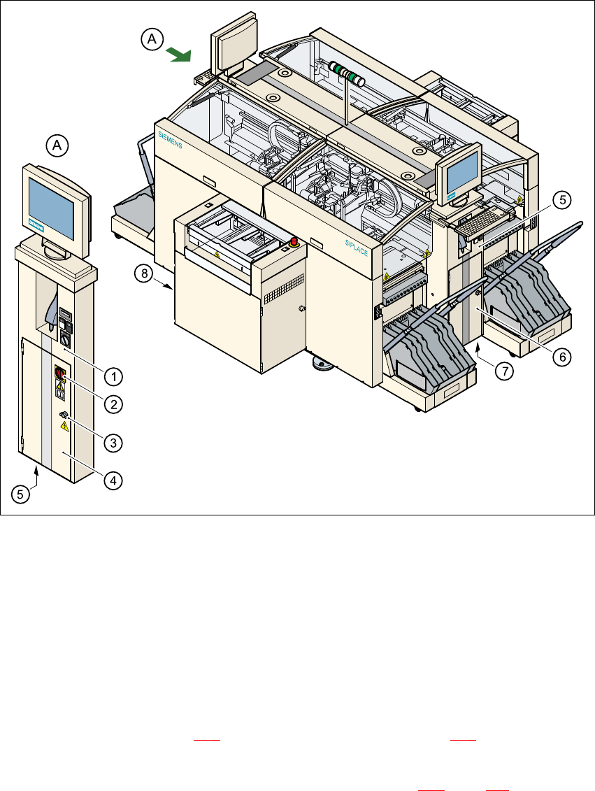
Fig. 8 - 7 Accessing the power supply unit
(1) Operator panel, left-hand side
(2) Main switch
(3) Door lock
(4) Protective doors to power supply unit
(5) Hole for power cable
Open the lock (item 3 in Fig. 8 - 7) on the protective door (item 4 in Fig. 8 - 7 using the machine
key.
Use the Allen key to loosen the M8 locking screw (item M8 in Fig. 8 - 8, page 269) on the lower
front panel.
Pull the power supply unit out as far as the stop.