00193437-03_AI_PowerSupplyConversion_DE+EN.pdf - 第198页
5 Converting the power supply on S-27 HM machines/ and on component trolleys Assembly Instructions, Converting the Power Supply 5.6 Converting the S-27 HM from 3 x 400 VAC to 3 x 208 VAC 12/2013 Edition 196 Fig. 5 - 3 Po…

Assembly Instructions, Converting the Power Supply 5 Converting the power supply on S-27 HM machines/ and on component trolleys
12/2013 Edition 5.6 Converting the S-27 HM from 3 x 400 VAC to 3 x 208 VAC
195
5.6.2 Converting the single-phase transformer T1 from 230 VAC to 120 VAC
Detach the black connecting wire from terminal (6) (230 VAC) and connect to terminal (4)
(120 VAC) (see Fig. 5 - 2
).
5.6.3 Converting the three-phase transformer T2 from 3 x 400 VAC to 3 x 208 VAC
Detach the black connecting wire from terminal 1 U1 (400 VAC) and connect to terminal 1U3
(208 VAC) (see Fig. 5 - 2
).
Detach the black connecting wire from terminal 1 V1 (400 VAC) and connect to terminal 1V3
(208 VAC) (see Fig. 5 - 2
).
Detach the black connecting wire from terminal 1 W1 (400 VAC) and connect to terminal 1W3
(208 VAC) (see Fig. 5 - 2
).
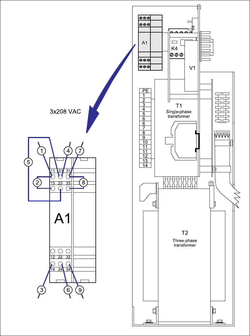
5.6.4 Converting the inrush current limiter A1 from 3 x 400 VAC to 3 x 208 VAC
Detach wire (3) from terminal 13 and connect to terminal 14 (see Fig. 5 - 3).
Detach wire (6) from terminal 23 and connect to terminal 24 (see Fig. 5 - 3).
Detach wire (9) from terminal 33 and connect to terminal 34 (see Fig. 5 - 3).
Detach wire (2) from terminal 12 and connect to terminal 13 (see Fig. 5 - 3).
Detach wire (5) from terminal 22 and connect to terminal 23 (see Fig. 5 - 3).
Detach wire (8) from terminal 32 and connect to terminal 33 (see Fig. 5 - 3).
5.6.5 Installing the power supply unit
Carefully push the power supply unit into the housing until it reaches the stop.
Use the hexagon socket-head screw to secure the unit at the bottom.
Check that the yellow-green PE wire is connected to the cover.
Replace the cover.
PLEASE NOTE: 5
Make sure that the actuating shaft of the main switch slides easily into the opening in the ro-
tary button. 5
Fix the cover in place using the two hexagon socket head screws.
5 Converting the power supply on S-27 HM machines/ and on component trolleys Assembly Instructions, Converting the Power Supply
5.6 Converting the S-27 HM from 3 x 400 VAC to 3 x 208 VAC 12/2013 Edition
196
Fig. 5 - 3 Power supply unit front - connecting the inrush current limiter (003429988-01)
for 3 x 208 VAC
1 - 9 Numbers of the connecting wires
A1 Inrush current limiter 5
Assembly Instructions, Converting the Power Supply 5 Converting the power supply on S-27 HM machines/ and on component trolleys
12/2013 Edition 5.6 Converting the S-27 HM from 3 x 400 VAC to 3 x 208 VAC
197
5.6.6 5 or 4-wire connection for the power supply
The connections are produced using either 5 or 4 wires, according to the electricity company's re-
quirements. The placement machine is supplied with a 5-wire connection as standard. 5
5.6.6.1 5-wire connection
In the 5-wire connection, the neutral conductor (NE) and protective earth (PE) consist of separate
wires. 5
Two additional yellow-green jumper cables BR1 and BR2 are connected to terminal strips
X206:PE and X207:7 in the "Voltages" terminal panel. These jumper cables are then recon-
nected for a 4-wire connection.
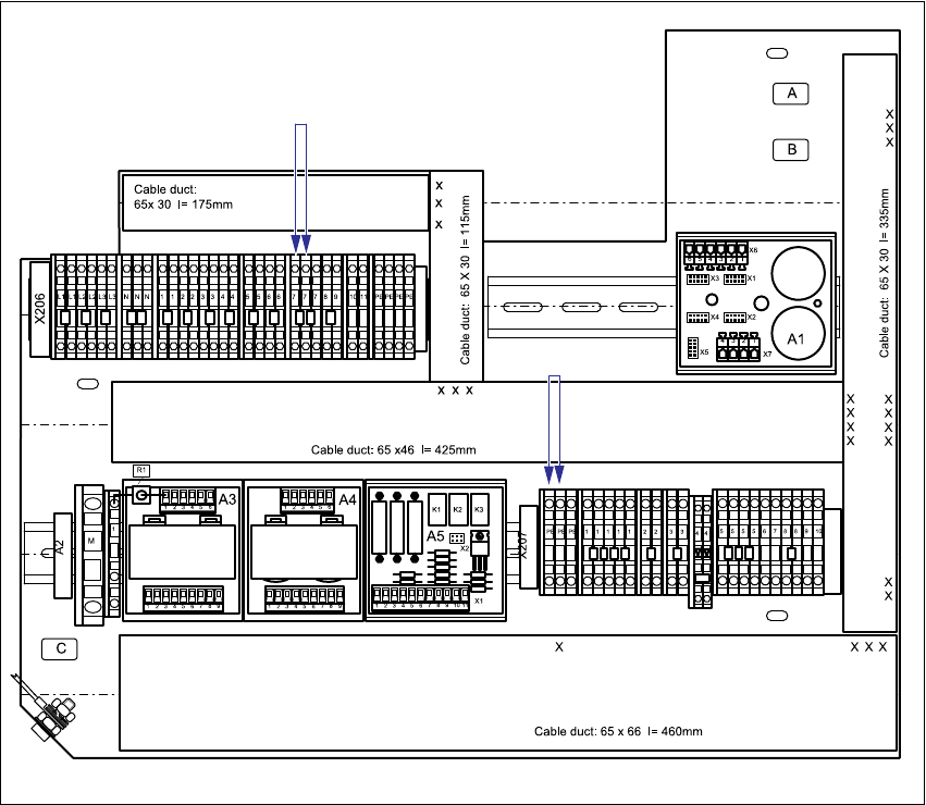
Fig. 5 - 4 Terminal panel "Voltages", 5-wire connection
JMP1 (yegn) 5
JMP2 (yegn) 5