00193437-03_AI_PowerSupplyConversion_DE+EN.pdf - 第187页
Assembly Instructions, Converting the Power S upp ly 4 Converting the power supply o n the MTC2 12/2013 Edition 4.5 Converting the power supply from 3 x 208 VAC to 3 x 400 VAC 185 4.4.2 Checking the protective wire conne…
4 Converting the power supply on the MTC2 Assembly Instructions, Converting the Power Supply
4.4 Converting the power supply from 3 x 400 VAC to 3 x 208 VAC 12/2013 Edition
184
4
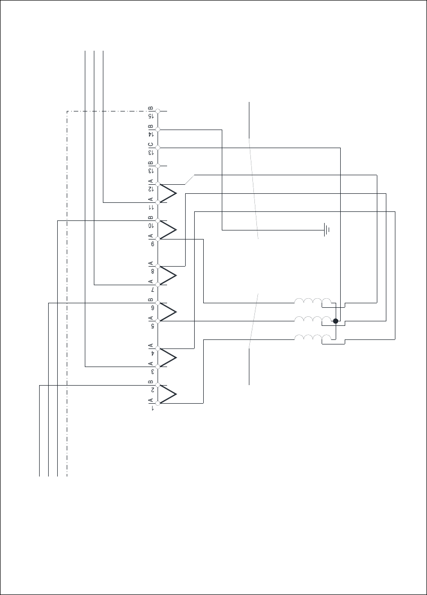
Fig. 4 - 3 MTC2 - terminal panel X01, circuit diagram 3 x 208 VAC
1V1
1 2 3
2U1
2V1
2W1
4x2.5mm² CSA
1W1
1U1
3.7 kVA /50-60Hz
Oilflex 190
-W003
Transformer T1
3 x 208 VAC / 3 x 400 VAC
3 x 208 VAC / 120 VAC
L1
L2
50Hz / 60 Hz
L3
PE
X01 terminal block
5x2.5mm² CSA
1 2 3 4
Oilflex 190
-W004
PE
L3.1
L1.1
L2.1
C
A A
JMPJMP JMPJMP JMPJMPJMP: 3 x 208 VAC
N

Assembly Instructions, Converting the Power Supply 4 Converting the power supply on the MTC2
12/2013 Edition 4.5 Converting the power supply from 3 x 208 VAC to 3 x 400 VAC
185
4.4.2 Checking the protective wire connections, fitting the covers
Check that the detached protective earth wires have been reconnected correctly.
Fit the cover.
4.4.3 Carry out the safety check to DIN EN 60 204
When the conversion is complete, carry out a safety check to DIN EN 60 204.
Follow the procedure described in section 2, page 146 onwards.
4
4.5 Converting the power supply from 3 x 208 VAC to 3 x 400 VAC
Dock the MTC2 out of the placement machine.
RISK OF DEATH 4
Disconnect the MTC2 from the main power supply.
Remove the plug for the communication cable from the placement machine.
Take suitable action to ensure that the MTC2 cannot be connected to the power supply during
the conversion work.
Put up warning signs to indicate that work is being carried out on the electrical system.
4 Converting the power supply on the MTC2 Assembly Instructions, Converting the Power Supply
4.5 Converting the power supply from 3 x 208 VAC to 3 x 400 VAC 12/2013 Edition
186
4.5.1 Conversion work on the electronic panel
4
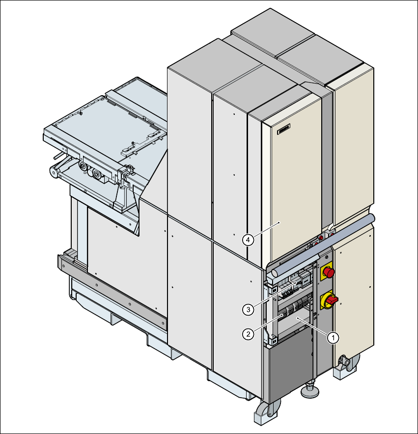
Fig. 4 - 4 Position of the electronic panel
(1) Electronic panel
(2) Terminal block X01
(3) Motor contactor Q01
(4) Door, left-hand side
Open the left door.
Release the screws for the electronic panel cover.
Lift off the cover.