User Manual SIPLACE MeasuringFeeder X.pdf - 第12页
2 Operational Safety 2.2 ESD Guidelines 12 User Manual SIPLACE MeasuringFeeder X 03/2020 2.2.5 Dispatching ESD Modules ► Always store modules and components in conductive packaging (e.g. metalized plastic bags or metal s…

2 Operational Safety
2.2 ESD Guidelines
User Manual SIPLACE MeasuringFeeder X 03/2020 11
2.2 ESD Guidelines
2.2.1 Definition of ESD
Almost all of the modules in use today are equipped with highly integrated MOS blocks and com-
ponents. The manufacturing techniques used mean that these electronic components are ex-
tremely sensitive to overvoltage and thus to electrostatic discharge.
Fig.1: ESD label
The abbreviation for such modules is "ESD"(Electrostatic Sensitive
Device). This is used internationally, although the German abbreviation
"EGB" may also be seen. The following symbol on cabinet rating plates,
racks or packaging indicates that components which are sensitive to elec-
trostatic discharge have been used and thus that the modules concerned
are also touch-sensitive.
ESDs can be destroyed by voltages and electrostatic charges that are far below the level that can
be perceived by humans. Such voltages occur if a person touches a component or module
without earthing themselves. Components that are exposed to such overvoltage do not generally
appear to be defective immediately - incorrect behavior starts after the component or module has
been in operation for some time.
2.2.2 Important Measures to Protect Against Static Charging
► Most plastics can easily become charged and must therefore be kept away from at-risk com-
ponents.
► Always ensure that people, the workplace and packaging are safely earthed when handling
electrostatic sensitive components.
2.2.3 Handling ESD Modules
Do not touch electronic modules unless it is absolutely essential to do so in order to carry out other
work. If it is necessary, make sure that you do not touch the pins or printed conductors when you
pick up flat modules.
Do not touch components unless
●
You are constantly earthed by an ESD wrist strap or
●
You are wearing ESD shoes or ESD shoe earthing strips on an ESD floor.
Always discharge yourself before you touch an electronic module. To do this, simply touch a con-
ductive and earthed object immediately before you touch the module (such as unpainted parts of a
switch cabinet, a water pipe, etc.).
Do not allow modules with chargeable and highly insulating materials to touch one another, e.g.
plastic films, insulating table surfaces or items of clothing made from synthetic fibers.
Always place the modules on a conductive surface (table with an ESD coating, conductive ESD
foam, ESD bag or container).
Do not bring modules near visual display units, monitors or televisions. Keep them at least 10cm
away from the screen.
2.2.4 Measurements and Modifications to ESD Modules
Measurements of the assemblies may only be taken if
●
The measuring device has been grounded (e.g. via protective conductor) or
●
you discharge the measuring head before taking measurements with a potential-free measur-
ing device (e.g. by touching an unpainted metal part of the controller casing).
► Always use an earthed soldering iron if you carry out any soldering work.

2 Operational Safety
2.2 ESD Guidelines
12 User Manual SIPLACE MeasuringFeeder X 03/2020
2.2.5 Dispatching ESD Modules
► Always store modules and components in conductive packaging (e.g. metalized plastic bags
or metal sleeves) and dispatch them in conductive packaging.
► If the packaging is not conductive, place the modules in a conductive envelope before pack-
aging. Use conductive expanded rubber, ESD bags, domestic aluminum foil or paper, for
example.
► If the module has integral batteries, ensure that the conductive packaging does not touch or
short-circuit the battery terminals and, if necessary, first cover the terminals with insulating
tape or material.
3 Function Description and Design
3.1 Function Description
User Manual SIPLACE MeasuringFeeder X 03/2020 13
3 Function Description and Design
3.1 Function Description
In some industries, it is of high importance to verify the electrical characteristics of components
before they are placed on a printed circuit board (PCB). Components could be defective, they could
have the wrong label on the packaging or they could even be fake components without function.
The time delay between placement and an electrical test like an In-Circuit-Test (ICT) is typically
fairly long and it's important so save that time by verifying the authenticity and integrity of the
component already during placement. Some components cannot be tested with an ICT because of
the electrical circuit they are installed in.
Usually, it is not necessary to test every component but rather do random inspections in every lot.
The very first component out of each tape is always measured in order to verify that the setup is
correct.
The MeasuringFeeder X can measure the electrical value of a component. To determine the value
correctly, the MeasuringFeeder X needs to know the component type to be measured. To reduce
measurement time, the MeasuringFeeder X also needs to know the target values in order to set the
correct measurement range. Component types and their corresponding target values are pre-selec-
ted in the line software (SIPLACE Pro) during production planning.
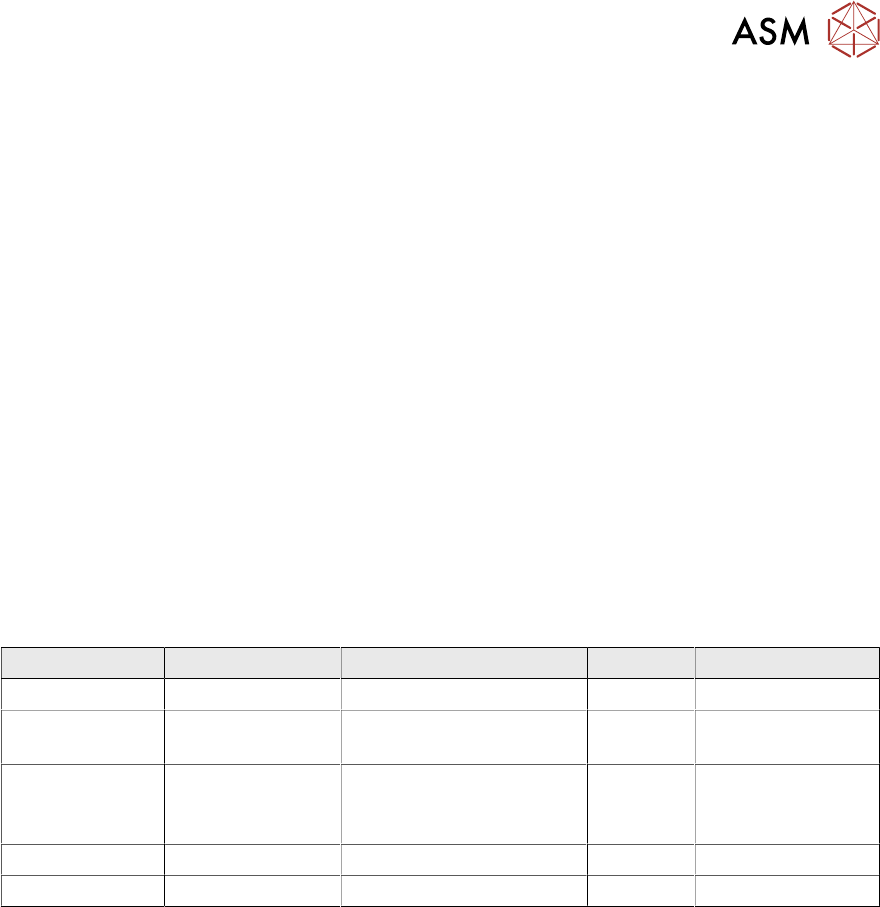
The following table shows the measurement ranges of the different component types that can be
pre-selected in the line software:
Type ValueRange Measurement Accuracy Polarity Additional Value
Resistor 0.1Ω to 1MΩ ±5% +0 mΩ / -200 mΩ No -
Standard
Capacitor
1) 3)
1pF to 100µF ±5% +5 pF / -2 pF No -
Polarized
Capacitor
1) 3)
100nF to 500µF ±5% +5 pF / -2 pF No Rated Voltage
(Volt) 3.6to60
default: 35
Inductor
1)
1µH to 1mH ±15% No -
Diode 0.2V to 4.0V ±10% ±100 mV
2)
Yes -
Orientation corresponds to IPC7315 (Pin 1 left side)
1)
At a measurement frequency of 1 kHz or 10 kHz (depending on component value)
2)
At a measurement current of typically 10 mA
The MeasuringFeeder X supports the following component sizes:
●
Chip components: 0201 up to 1210
●
Other components: 0.6 mm x 0.3 mm up to 6.0 mm x 3.2 mm
3)
The capacity measurement of a capacitor depends on the frequency and the voltage which is ap-
plied to the capacitor. It is also depending on the class of capacitor. The class 1 capacitors are not
impacted by the voltage and the frequency. But class 2 and 3 show a significant dependency.
The manufacturers of class 2 and class 3 capacitors typically specify for the measurement of the
capacity conditions (frequency & voltage) which are close to typical use cases. Only if the recom-
mended frequency and voltage (from the data sheet) is applied during the measurement, the nom-
inal capacity can be measured.
The MeasuringFeeder X can provide two frequencies 1 kHz or 10 kHz and a limited voltage range
depending on the frequency.