User Manual SIPLACE MeasuringFeeder X.pdf - 第19页
4 Operation 4.1 Settings in the Line Software User Manual SIPLACE MeasuringFeeder X 03/2020 19 4 Operation 4.1 Settings in the Line Software In order to use the MeasuringFeeder X in a placement task, the appropriate sett…

3 Function Description and Design
3.2 Design
18 User Manual SIPLACE MeasuringFeeder X 03/2020
4 Operation
4.1 Settings in the Line Software
User Manual SIPLACE MeasuringFeeder X 03/2020 19
4 Operation
4.1 Settings in the Line Software
In order to use the MeasuringFeeder X in a placement task, the appropriate settings must be
defined in the line software (SIPLACE Pro, version 15.0 or later) during production planning:
●
Integrating the MeasuringFeeder X in the current machine setup
●
Defining the electrical characteristics of components
●
Marking the components that shall be measured
●
Defining the measurement occurrence of a component
●
Selecting the nozzles for measuring and / or placement of a component shape
4.1.1 Setting up the MeasuringFeeder X
The MeasuringFeeder X must be integrated in the current machine setup in order to use it for
measuring components. The MeasuringFeeder X can be set up on any track of a changeover table
that the placement head is able to reach. The MeasuringFeeder X occupies one track on a
changeover table.
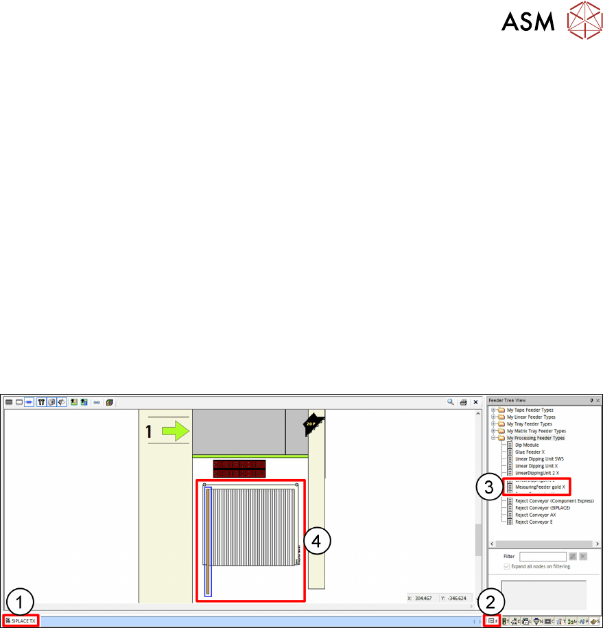
► Click on the tab(1) of the current setup.
► Click on the Feeder Tree View tab(2).
► Select the MeasuringFeeder X from the Feeder Tree View(3) and drag it onto the appro-
priate track on the changeover table(4).
4 Operation
4.1 Settings in the Line Software
20 User Manual SIPLACE MeasuringFeeder X 03/2020
4.1.2 Defining the Electrical Characteristics of a Component
Resistors
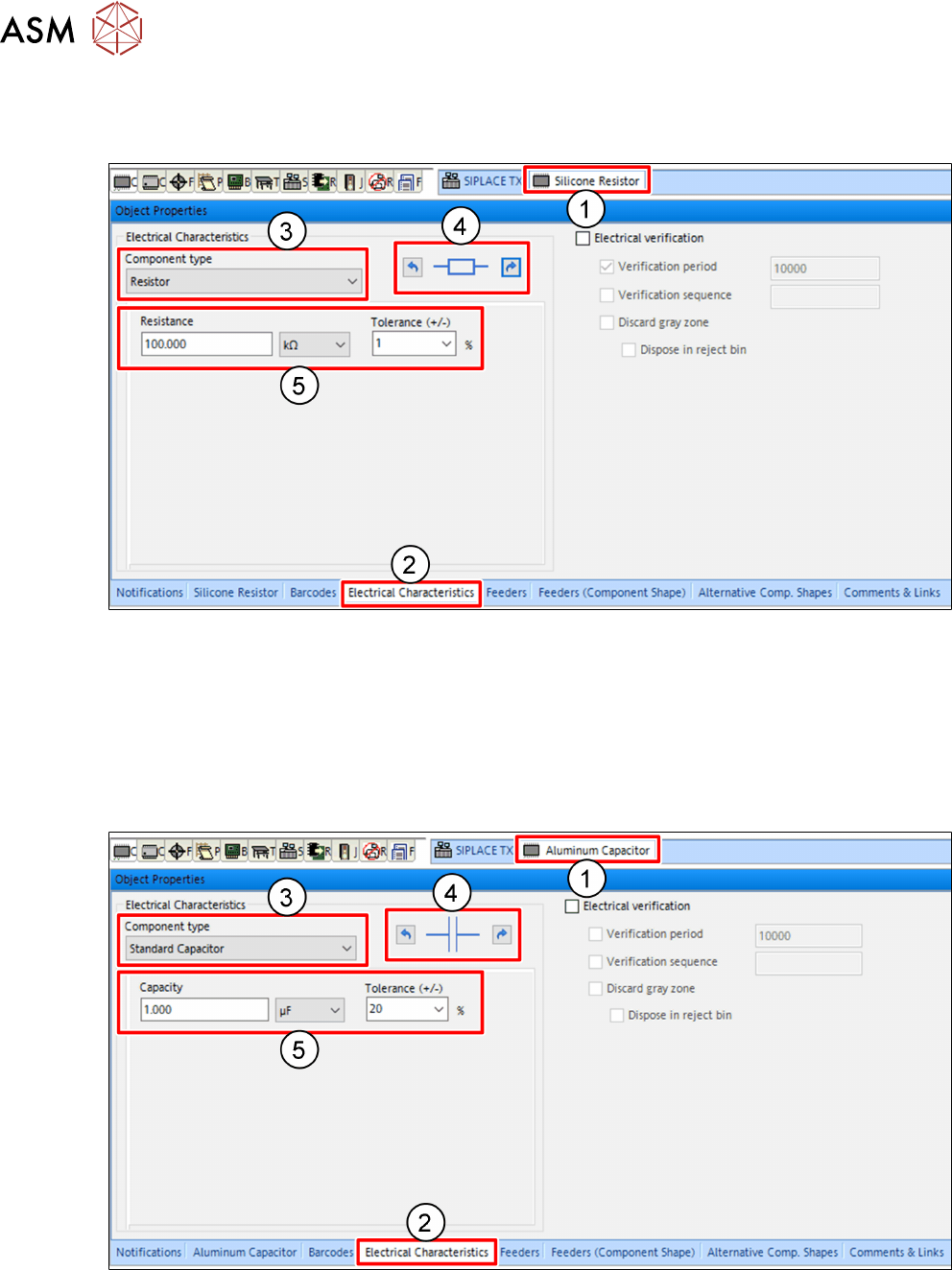
► Click on the tab(1) of the particular component.
► Click on the Electrical Characteristics tab(2) of the Object Properties view.
► In the Electrical Characteristics area, select Resistor from the Component type drop down
menu(3).
► Adjust the electrical orientation of the component(4) if necessary.
► Enter the expected electrical values of the component(5).
Standard Capacitors
► Click on the tab(1) of the particular component.
► Click on the Electrical Characteristics tab(2) of the Object Properties view.
► In the Electrical Characteristics area, select Standard Capacitor from the Component
type drop down menu(3).
► Adjust the electrical orientation of the component(4) if necessary.
► Enter the expected electrical values of the component(5).