User Manual SIPLACE MeasuringFeeder X.pdf - 第17页
3 Function Description and Design 3.2 Design User Manual SIPLACE MeasuringFeeder X 03/2020 17 3.2.4 Control Panel The control panel on the MeasuringFeeder X consists of a status-LED and the removal handle to dock and und…
3 Function Description and Design
3.2 Design
16 User Manual SIPLACE MeasuringFeeder X 03/2020
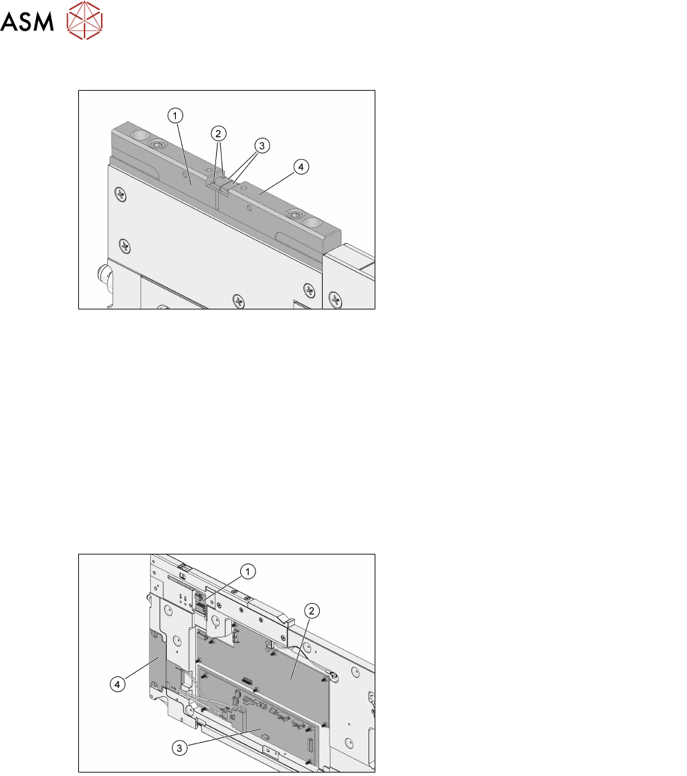
3.2.2 Contact Module
1. Contact plate holder
2. Fiducial points
3. Contact plates
4. Contact plate holder
The contact module is protected by a manual protective cover that should be closed if the
MeasuringFeeder X is not docked to a machine. The cover should be opened before docking the
MeasuringFeeder X. The open-state of the cover is monitored by a sensor. If the protective cover is
still closed after initialization, the operator is informed via an error message in the station software
(see chapter 4.3 "Positioning and Docking the MeasuringFeeder X" [}27]).
There are two fiducial points on each of the contact plates that can be viewed by the PCB-camera
to exactly locate the measuring positions for the components. The determination of the position of
the fiducial points is done during the reference run.
The contact plate can handle components from 0201 (= 0.6 mm x 0.3mm) to 6.0mm x3.2mm.
The contact plate holders are made from a non-conductive material and electrically isolate the con-
tact plates for maximum accuracy of the measurement.
3.2.3 Electronic Components
1. Contact module board
2. Measurement board
3. Control board
4. EDIF (Energy and Data Interface)
The contact module board carries an EEPROM for data storage as well as interface connectors to
the contact plates and the measurement board.
The measurement board carries the protective cover optical sensor as well as the control and
measurement electronics.
The control board is the central instance that controls all functions of the MeasuringFeeder X and
the communication with the placement machine.
The EDIF provides a contact-less power and data transfer between the MeasuringFeeder X and
the placement machine.
3 Function Description and Design
3.2 Design
User Manual SIPLACE MeasuringFeeder X 03/2020 17
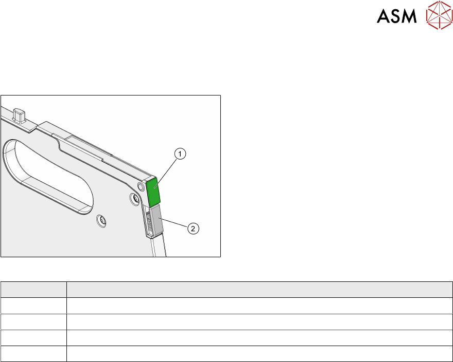
3.2.4 Control Panel
The control panel on the MeasuringFeeder X consists of a status-LED and the removal handle to
dock and undock the module from the changeover table.
1. Status-LED
2. Removal handle
The status-LED displays the current operational state of the MeasuringFeeder X:
Color
Green The MeasuringFeeder X is docked, functional and active in the current setup.
Orange Indicates a warning.
Red An error has occurred.
Off The MeasuringFeeder X is not docked or not active in the current setup.

3 Function Description and Design
3.2 Design
18 User Manual SIPLACE MeasuringFeeder X 03/2020