User Manual SIPLACE MeasuringFeeder X.pdf - 第25页
4 Operation 4.1 Settings in the Line Software User Manual SIPLACE MeasuringFeeder X 03/2020 25 The „Discard gray zone“ check box(3) is cleared. All components from the Gray Zone are placed. The machine first places the …
4 Operation
4.1 Settings in the Line Software
24 User Manual SIPLACE MeasuringFeeder X 03/2020
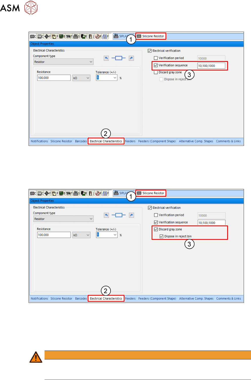
Defining a Verification Sequence
► Click on the tab(1) of the particular component.
► Click on the Electrical Characteristics tab(2) of the Object Properties view.
► Mark the Verification sequence check box(3).
► Enter the values in the entry field(3). The values must be separated by a semicolon.
Defining the Behavior at a Gray Zone
► Click on the tab(1) of the particular component.
► Click on the Electrical Characteristics tab(2) of the Object Properties view.
► Mark the Discard gray zone check box(3).
ð The components in the gray zone are not measured and not placed.
► Mark the Dispose in reject bin check box(3).
ð Every component in the gray zone is picked up and disposed in the reject bin.
WARNING
Danger of Fire
Tantalum capacitors should always be disposed in the reject bin. If they remain in the tape,
they could be hit by the tape cutter and catch fire.
4 Operation
4.1 Settings in the Line Software
User Manual SIPLACE MeasuringFeeder X 03/2020 25
The „Discard gray zone“ check box(3) is cleared.
All components from the Gray Zone are placed. The machine first places the remaining compon-
ents from the old tape and then from the new tape until the estimated "Gray Zone" is completed.
Afterwards a measurement with a component from the new tape is performed.
4.1.5 Selecting the Nozzles for Measuring and Placement
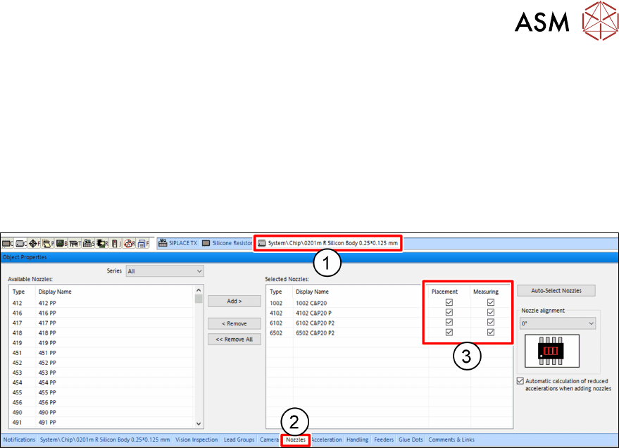
For each particular component shape, one or more nozzles must be selected to operate that
component shape. If a component is marked for electrical verification, at least one nozzle must be
selected for measuring:
► Click on the tab(1) of the particular component shape.
► Click on the Nozzles tab(2) of the Object Properties view.
The Selected Nozzles table shows all nozzles that have been selected to operate this particular
component shape.
► For every selected nozzle, mark if it shall be used for placement and / or measuring(3) this
particular component shape.
4 Operation
4.1 Settings in the Line Software
26 User Manual SIPLACE MeasuringFeeder X 03/2020
4.1.6 Using Special Nozzles for Measuring Small Components
Small chip components of the types 0201, 0402, 0603, 0805, 1206, and 1210 can typically not be
measured using a standard nozzle, because their contacts extend to the top side. The available
standard nozzles usually have a low resistance. If such a nozzle touches one or both contacts of
the component, then a fraction of the measurement current can flow through the nozzle. This im-
pairs the result of the measurement. To avoid this problem, there is a set of special nozzles avail-
able that have a very high resistance.
NOTICE
Special Measuring Nozzles in SIPLACE Pro
The special nozzles for measuring small chip components are not part of the standard
nozzle set in SIPLACE Pro. They need to be defined in the nozzles editor. See the
SIPLACE Pro documentation about how to do this.
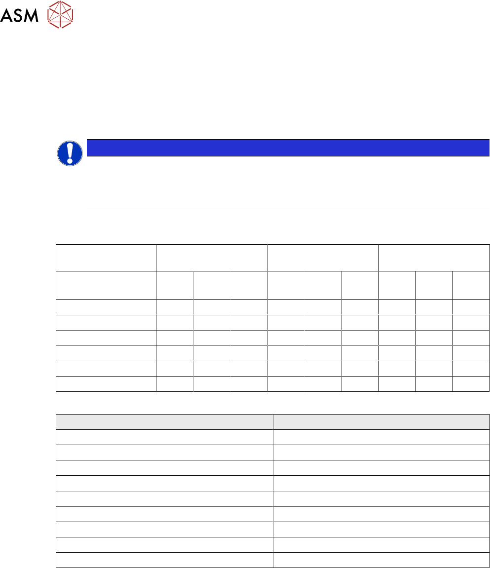
The following table lists the suggested combinations of component shapes, placement heads and
special measuring nozzles:
Placement Head CPP / CPPM CP20 / CP20A / CP20M CP20P / CP20M /
CP20M2 / CP20P2
Nozzle
Component
2403
M
2404
M
2406
M
1403
M
1404
M
1406
M
4403
M
4404
M
4406
M
0201 ✓ ✓ ✓
0402 ✓ ✓ ✓
0603 ✓ ✓ ✓
0805 ✓ ✓ ✓
1206 ✓ ✓ ✓
1210 ✓ ✓ ✓
The following table lists the item numbers of the special measuring nozzles:
Nozzle Type Item Number
2403 cpl. M/ ceramic 03206825-xx
2404 cpl. M/ ceramic 03206826-xx
2406 cpl. M/ ceramic 03206827-xx
1403 cpl. M/ ceramic 03206822-xx
1404 cpl. M/ ceramic 03206823-xx
1406 cpl. M/ ceramic 03206824-xx
4403 cpl. M/ ceramic 03206829-xx
4404 cpl. M/ ceramic 03206828-xx
4406 cpl. M/ ceramic 03206830-xx