User Manual SIPLACE MeasuringFeeder X.pdf - 第28页
4 Operation 4.3 Positioning and Docking the MeasuringFeeder X 28 User Manual SIPLACE MeasuringFeeder X 03/2020 ► Position the MeasuringFeeder X on the appropriate guide rail on the changeover table. ► Carefully push the …
4 Operation
4.2 Handling the MeasuringFeeder X
User Manual SIPLACE MeasuringFeeder X 03/2020 27
4.2 Handling the MeasuringFeeder X
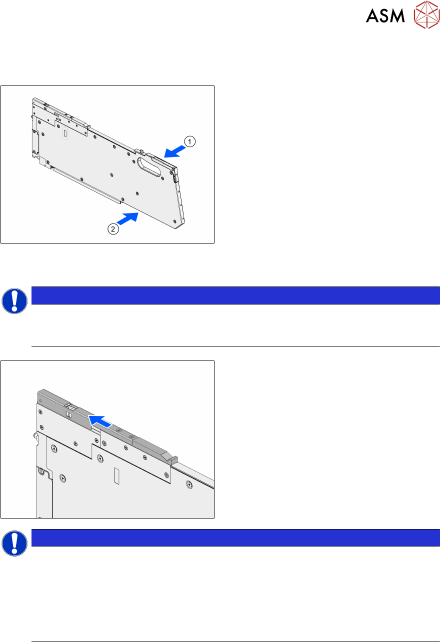
The MeasuringFeeder X provides a carrying handle for easy and safe transport.
► Grab the MeasuringFeeder X with one
hand at the carrying handle(1).
► If necessary, support the MeasuringFeeder
X with the other hand at the position indic-
ated in the image(2).
4.3 Positioning and Docking the MeasuringFeeder X
NOTICE
Positioning the MeasuringFeeder X in the correct guide rail
► Position the MeasuringFeeder X in the guide rail that was selected in the setup (see
chapter 4.1.1 "Setting up the MeasuringFeeder X" [}19]).
► Open the protective cover.
NOTICE
Protective cover is closed during operation or optical sensor is defect
The open-state of the protective cover is monitored by an optical sensor. If the protective
cover is still closed after initialization, the station software displays an error message (error
code 45100: Shutter of MeasuringFeeder X closed).
► Open the protective cover
► Check the optical sensor for defect, if the message is displayed although the protect-
ive cover is open.
4 Operation
4.3 Positioning and Docking the MeasuringFeeder X
28 User Manual SIPLACE MeasuringFeeder X 03/2020
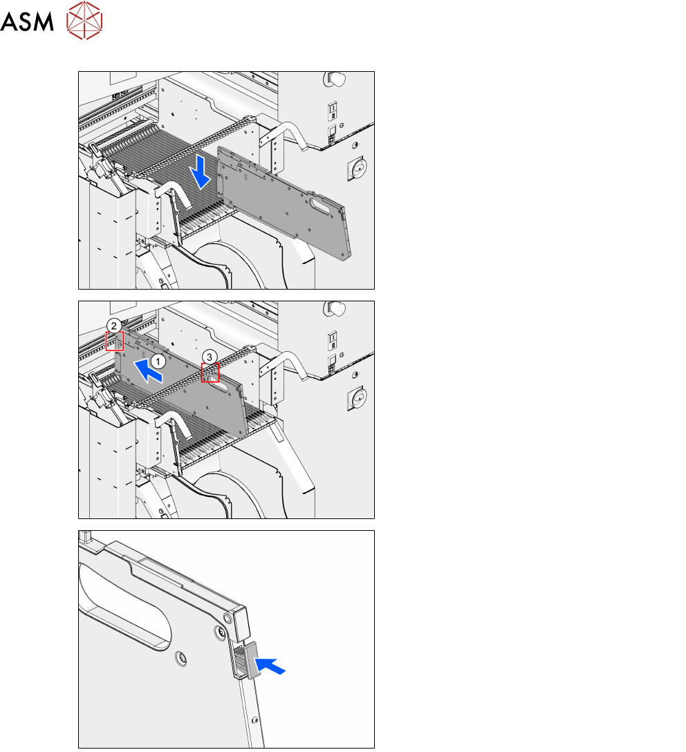
► Position the MeasuringFeeder X on the
appropriate guide rail on the changeover
table.
► Carefully push the MeasuringFeeder X for-
ward(1) on the guide rail until the front
centering pin engages in the appropriate
centering hole(2).
► Make sure that the rear centering pin en-
gages in the correct slot in the centering
bar(3).
► If still protruding, push the removal handle
fully in and release.
The login procedure is started.
The status-LED lights up green when the login procedure was completed successfully, if the
MeasuringFeeder X is included in the current setup and if it is installed on the correct guide rail.
The MeasuringFeeder X is now prepared for operation.
4 Operation
4.4 Measuring Components
User Manual SIPLACE MeasuringFeeder X 03/2020 29
4.4 Measuring Components
The measurement of components during production is monitored and controlled in the station soft-
ware.
4.4.1 Measuring Components automatically
Components that were marked for measurement are automatically measured during production fol-
lowing the rules that were defined during production planning.
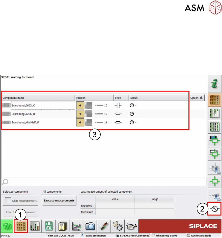
► Click on the Setup button (1).
► Click on the Measuring Units button (2).
The components list (3) displays all tracks with components that were marked for measurement
and their characteristics:
●
Component name
●
Location of the feeder
●
Electrical type of the component
●
Result of the last measurement
If a component is set up on more than one feeder, then it is listed several times.