User Manual SIPLACE MeasuringFeeder X.pdf - 第21页
4 Operation 4.1 Settings in the Line Software User Manual SIPLACE MeasuringFeeder X 03/2020 21 Polarized Capacitors ► Click on the tab (1) of the particular component . ► Click on the Electrical Characteristics tab (2)…
4 Operation
4.1 Settings in the Line Software
20 User Manual SIPLACE MeasuringFeeder X 03/2020
4.1.2 Defining the Electrical Characteristics of a Component
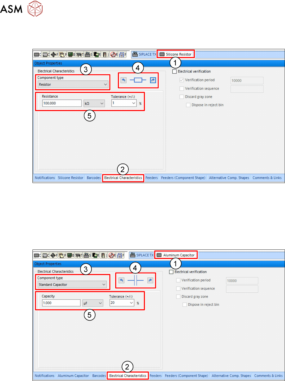
Resistors
► Click on the tab(1) of the particular component.
► Click on the Electrical Characteristics tab(2) of the Object Properties view.
► In the Electrical Characteristics area, select Resistor from the Component type drop down
menu(3).
► Adjust the electrical orientation of the component(4) if necessary.
► Enter the expected electrical values of the component(5).
Standard Capacitors
► Click on the tab(1) of the particular component.
► Click on the Electrical Characteristics tab(2) of the Object Properties view.
► In the Electrical Characteristics area, select Standard Capacitor from the Component
type drop down menu(3).
► Adjust the electrical orientation of the component(4) if necessary.
► Enter the expected electrical values of the component(5).
4 Operation
4.1 Settings in the Line Software
User Manual SIPLACE MeasuringFeeder X 03/2020 21
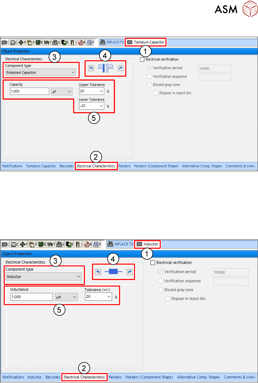
Polarized Capacitors
► Click on the tab(1) of the particular component.
► Click on the Electrical Characteristics tab(2) of the Object Properties view.
► In the Electrical Characteristics area, select Polarized Capacitor from the Component
type drop down menu(3).
► Adjust the electrical orientation of the component(4) if necessary.
► Enter the expected electrical values of the component(5).
Inductors
► Click on the tab(1) of the particular component.
► Click on the Electrical Characteristics tab(2) of the Object Properties view.
► In the Electrical Characteristics area, select Inductor from the Component type drop down
menu(3).
► Adjust the electrical orientation of the component(4) if necessary.
► Enter the expected electrical values of the component(5).
4 Operation
4.1 Settings in the Line Software
22 User Manual SIPLACE MeasuringFeeder X 03/2020
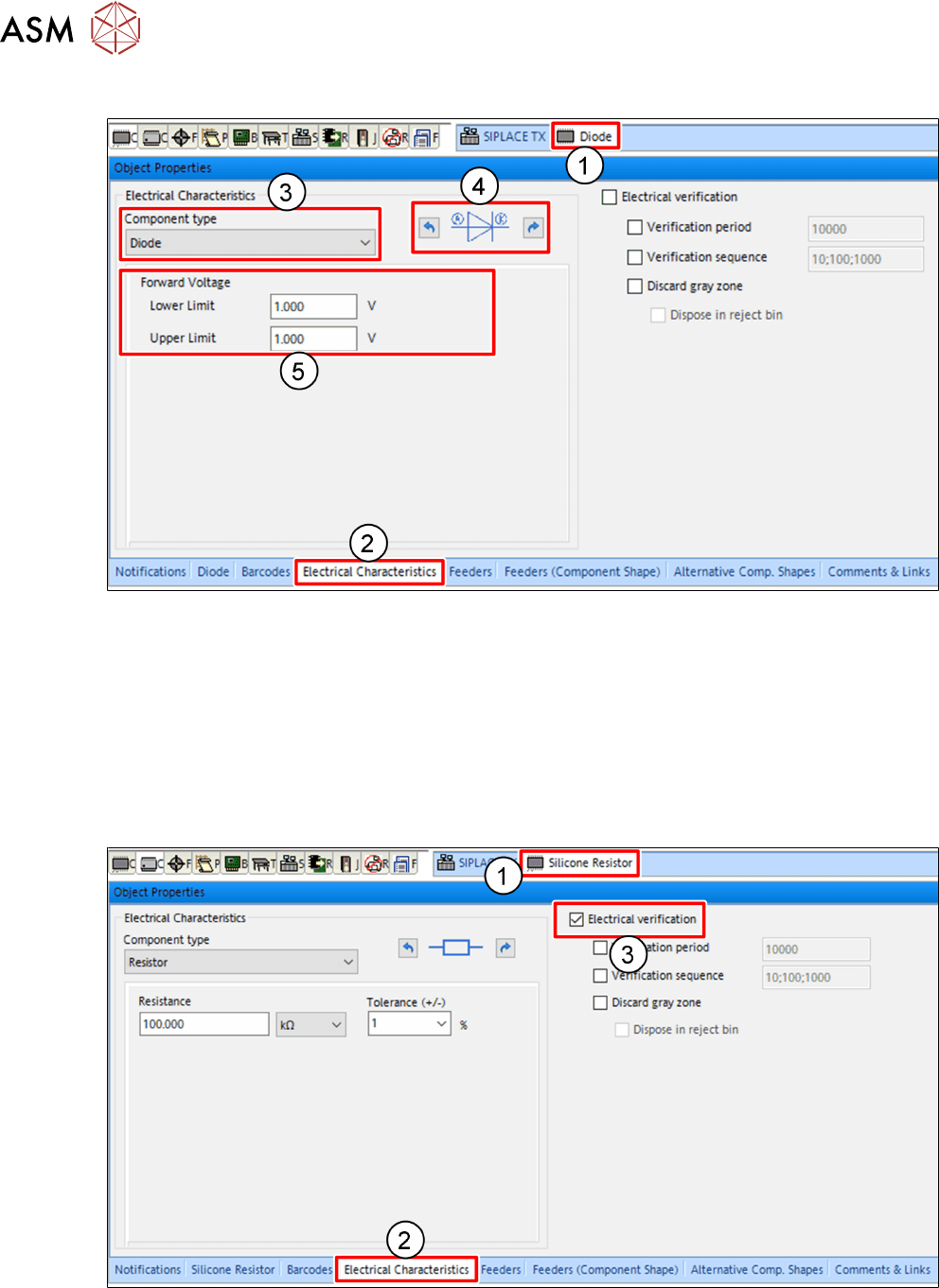
Diodes
► Click on the tab(1) of the particular component.
► Click on the Electrical Characteristics tab(2) of the Object Properties view.
► In the Electrical Characteristics area, select Diode from the Component type drop down
menu(3).
► Adjust the electrical orientation of the component(4) if necessary.
► Enter the expected electrical values of the component(5).
4.1.3 Marking a Component for Measuring
The procedure described here is explained using a resistor as an example.
► Click on the tab(1) of the particular component.
► Click on the Electrical Characteristics tab(2) of the Object Properties view.
► Mark the Electrical verification check box(3).