User Manual SIPLACE MeasuringFeeder X.pdf - 第16页
3 Function Description and Design 3.2 Design 16 User Manual SIPLACE MeasuringFeeder X 03/2020 3.2.2 Contact Module 1. Contact plate holder 2. Fiducial points 3. Contact plates 4. Contact plate holder The contact module i…
3 Function Description and Design
3.2 Design
User Manual SIPLACE MeasuringFeeder X 03/2020 15
The Results of the Measurement
In case the measured value does not match the target value including all tolerances, this can have
the following reasons:
●
The component is faulty
●
The component has the wrong label
●
The MeasuringFeeder X is defect
●
The contact plate is worn or dirty
●
The nozzle is conductive and touches the connectors of the component
●
The nozzle is contaminated with solder and touches the contacts of the component
In the event of such a measurement error, the operator is informed via a detailed error message.
Two options are available:
●
Perform another measurement
●
Skip measurement for that component.
A component that is measured will always be discarded. It's not possible to place a component
after measuring.
The Behavior in the Gray Zone after the Splicing Plate
The splicing plate connects the old component tape with the new component tape after splicing.
The exact position of the splicing plate on both tapes depends on the accuracy of the crimping pro-
cess by the operator. The splice sensor detects the first edge of the splicing plate. The distance
between the beginning of the plate and the beginning of the new tape depends on:
●
The accuracy of the splice sensor: how exactly can the sensor detect the first edge of plate?
●
The distance between the splicing plate and the new tape
In this gray zone it is unknown, if the component belongs to the old or the new tape. The operator
must decide how to deal with this grey zone in the placement process.
3.2 Design
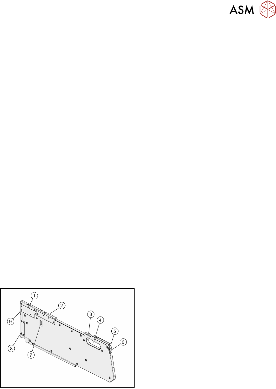
3.2.1 Overview
1. Measurement location with contact plates
2. Protective cover
3. Rear centering pin
4. Carrying handle
5. Status-LED
6. Removal handle
7. Calibration module interface
8. EDIF (Energy and Data Interface)
9. Front centering pin
3 Function Description and Design
3.2 Design
16 User Manual SIPLACE MeasuringFeeder X 03/2020
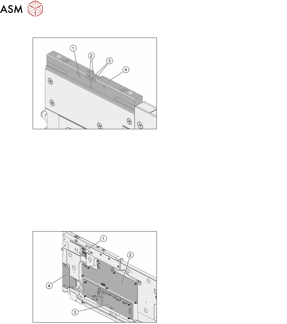
3.2.2 Contact Module
1. Contact plate holder
2. Fiducial points
3. Contact plates
4. Contact plate holder
The contact module is protected by a manual protective cover that should be closed if the
MeasuringFeeder X is not docked to a machine. The cover should be opened before docking the
MeasuringFeeder X. The open-state of the cover is monitored by a sensor. If the protective cover is
still closed after initialization, the operator is informed via an error message in the station software
(see chapter 4.3 "Positioning and Docking the MeasuringFeeder X" [}27]).
There are two fiducial points on each of the contact plates that can be viewed by the PCB-camera
to exactly locate the measuring positions for the components. The determination of the position of
the fiducial points is done during the reference run.
The contact plate can handle components from 0201 (= 0.6 mm x 0.3mm) to 6.0mm x3.2mm.
The contact plate holders are made from a non-conductive material and electrically isolate the con-
tact plates for maximum accuracy of the measurement.
3.2.3 Electronic Components
1. Contact module board
2. Measurement board
3. Control board
4. EDIF (Energy and Data Interface)
The contact module board carries an EEPROM for data storage as well as interface connectors to
the contact plates and the measurement board.
The measurement board carries the protective cover optical sensor as well as the control and
measurement electronics.
The control board is the central instance that controls all functions of the MeasuringFeeder X and
the communication with the placement machine.
The EDIF provides a contact-less power and data transfer between the MeasuringFeeder X and
the placement machine.
3 Function Description and Design
3.2 Design
User Manual SIPLACE MeasuringFeeder X 03/2020 17
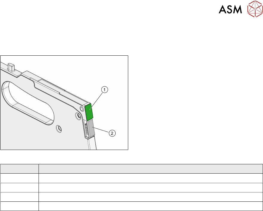
3.2.4 Control Panel
The control panel on the MeasuringFeeder X consists of a status-LED and the removal handle to
dock and undock the module from the changeover table.
1. Status-LED
2. Removal handle
The status-LED displays the current operational state of the MeasuringFeeder X:
Color
Green The MeasuringFeeder X is docked, functional and active in the current setup.
Orange Indicates a warning.
Red An error has occurred.
Off The MeasuringFeeder X is not docked or not active in the current setup.