User Manual SIPLACE MeasuringFeeder X.pdf - 第27页
4 Operation 4.2 Handling the MeasuringFeeder X User Manual SIPLACE MeasuringFeeder X 03/2020 27 4.2 Handling the MeasuringFeeder X The MeasuringFeeder X provides a carrying handle for easy and safe transport. ► Grab the …
4 Operation
4.1 Settings in the Line Software
26 User Manual SIPLACE MeasuringFeeder X 03/2020
4.1.6 Using Special Nozzles for Measuring Small Components
Small chip components of the types 0201, 0402, 0603, 0805, 1206, and 1210 can typically not be
measured using a standard nozzle, because their contacts extend to the top side. The available
standard nozzles usually have a low resistance. If such a nozzle touches one or both contacts of
the component, then a fraction of the measurement current can flow through the nozzle. This im-
pairs the result of the measurement. To avoid this problem, there is a set of special nozzles avail-
able that have a very high resistance.
NOTICE
Special Measuring Nozzles in SIPLACE Pro
The special nozzles for measuring small chip components are not part of the standard
nozzle set in SIPLACE Pro. They need to be defined in the nozzles editor. See the
SIPLACE Pro documentation about how to do this.
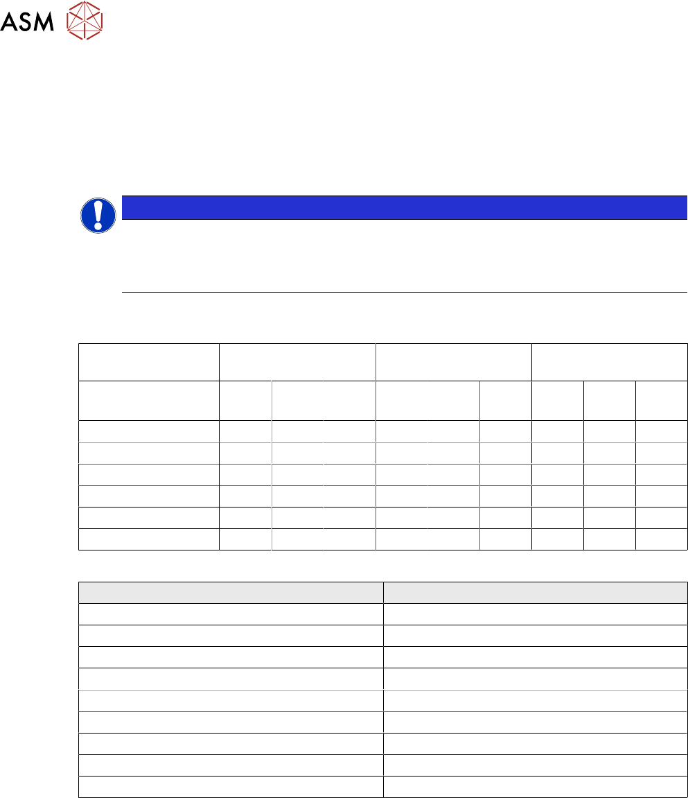
The following table lists the suggested combinations of component shapes, placement heads and
special measuring nozzles:
Placement Head CPP / CPPM CP20 / CP20A / CP20M CP20P / CP20M /
CP20M2 / CP20P2
Nozzle
Component
2403
M
2404
M
2406
M
1403
M
1404
M
1406
M
4403
M
4404
M
4406
M
0201 ✓ ✓ ✓
0402 ✓ ✓ ✓
0603 ✓ ✓ ✓
0805 ✓ ✓ ✓
1206 ✓ ✓ ✓
1210 ✓ ✓ ✓
The following table lists the item numbers of the special measuring nozzles:
Nozzle Type Item Number
2403 cpl. M/ ceramic 03206825-xx
2404 cpl. M/ ceramic 03206826-xx
2406 cpl. M/ ceramic 03206827-xx
1403 cpl. M/ ceramic 03206822-xx
1404 cpl. M/ ceramic 03206823-xx
1406 cpl. M/ ceramic 03206824-xx
4403 cpl. M/ ceramic 03206829-xx
4404 cpl. M/ ceramic 03206828-xx
4406 cpl. M/ ceramic 03206830-xx
4 Operation
4.2 Handling the MeasuringFeeder X
User Manual SIPLACE MeasuringFeeder X 03/2020 27
4.2 Handling the MeasuringFeeder X
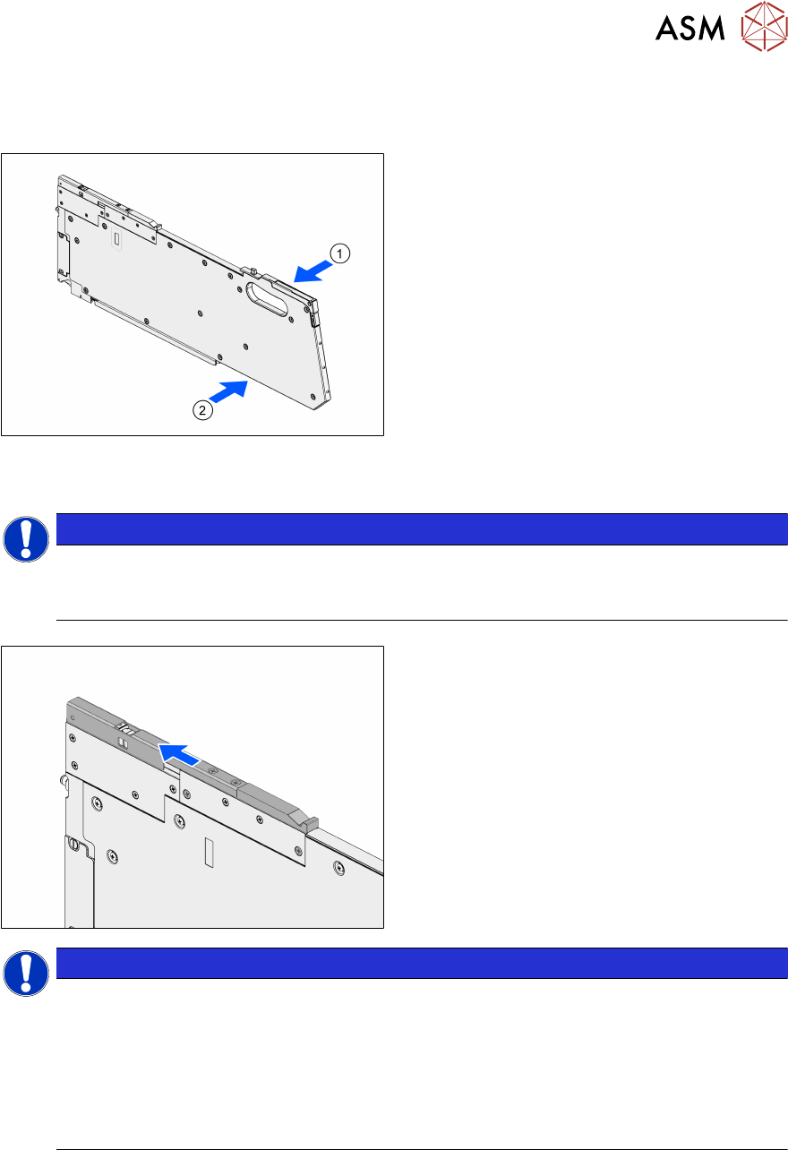
The MeasuringFeeder X provides a carrying handle for easy and safe transport.
► Grab the MeasuringFeeder X with one
hand at the carrying handle(1).
► If necessary, support the MeasuringFeeder
X with the other hand at the position indic-
ated in the image(2).
4.3 Positioning and Docking the MeasuringFeeder X
NOTICE
Positioning the MeasuringFeeder X in the correct guide rail
► Position the MeasuringFeeder X in the guide rail that was selected in the setup (see
chapter 4.1.1 "Setting up the MeasuringFeeder X" [}19]).
► Open the protective cover.
NOTICE
Protective cover is closed during operation or optical sensor is defect
The open-state of the protective cover is monitored by an optical sensor. If the protective
cover is still closed after initialization, the station software displays an error message (error
code 45100: Shutter of MeasuringFeeder X closed).
► Open the protective cover
► Check the optical sensor for defect, if the message is displayed although the protect-
ive cover is open.
4 Operation
4.3 Positioning and Docking the MeasuringFeeder X
28 User Manual SIPLACE MeasuringFeeder X 03/2020
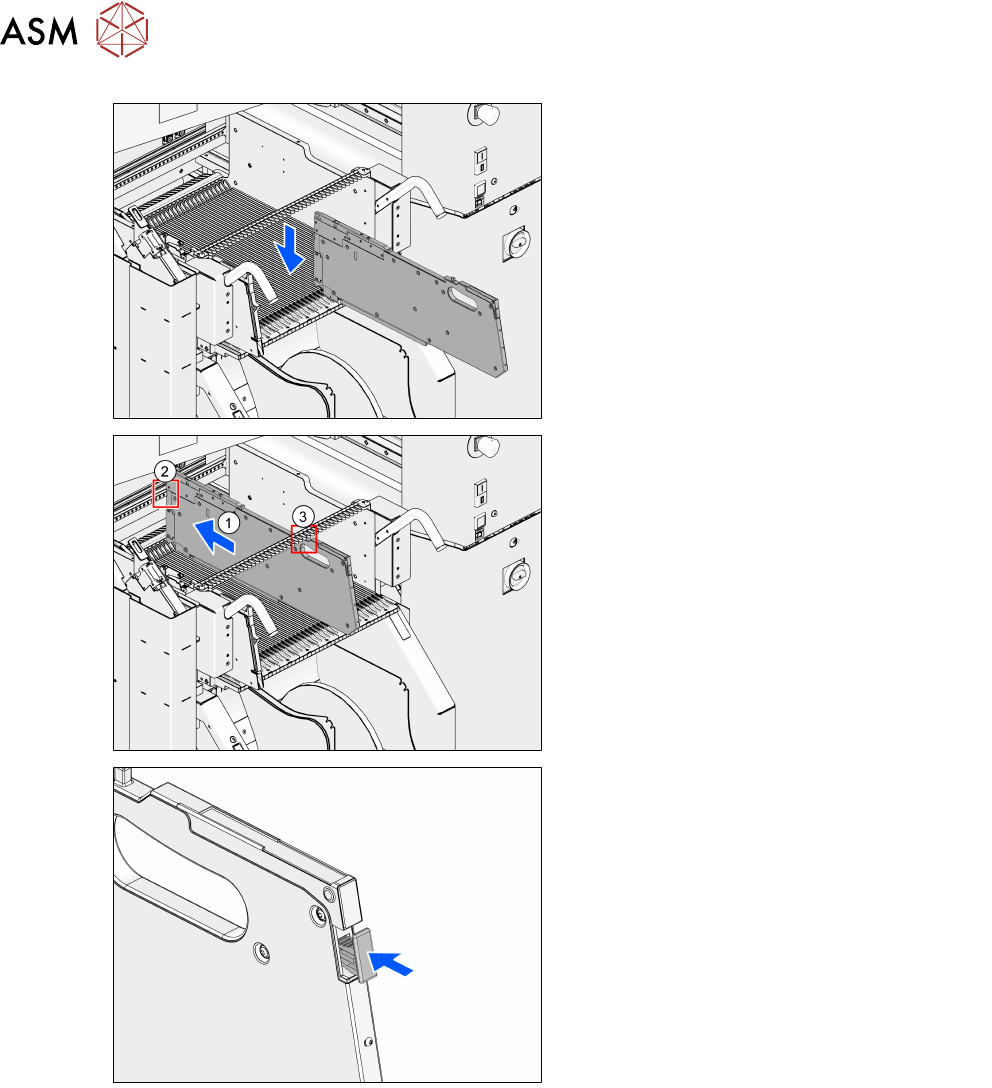
► Position the MeasuringFeeder X on the
appropriate guide rail on the changeover
table.
► Carefully push the MeasuringFeeder X for-
ward(1) on the guide rail until the front
centering pin engages in the appropriate
centering hole(2).
► Make sure that the rear centering pin en-
gages in the correct slot in the centering
bar(3).
► If still protruding, push the removal handle
fully in and release.
The login procedure is started.
The status-LED lights up green when the login procedure was completed successfully, if the
MeasuringFeeder X is included in the current setup and if it is installed on the correct guide rail.
The MeasuringFeeder X is now prepared for operation.