User Manual SIPLACE MeasuringFeeder X.pdf - 第24页
4 Operation 4.1 Settings in the Line Software 24 User Manual SIPLACE MeasuringFeeder X 03/2020 Defining a Verification Sequence ► Click on the tab (1) of the particular component . ► Click on the Electrical Characterist…
4 Operation
4.1 Settings in the Line Software
User Manual SIPLACE MeasuringFeeder X 03/2020 23
4.1.4 Defining Measurement Occurrence
If a component is selected for electrical verification, the first piece will be measured at each detec-
ted or potential package change, i.e. in case a new feeder is set up or after a foil torn error.
Optionally, an additional verification period can be defined if the component is to be measured
periodically. This value determines after how many pieces a component is measured again.
Optionally, an additional verification sequence can be defined: e.g. first check after 10, second
check after 100 and third check after 1000 components.
It also has to be specified how the individual components within the grey zone should be treated.
I.e., the components for which the system cannot determine to which packaging tape (old / new)
they belong to.
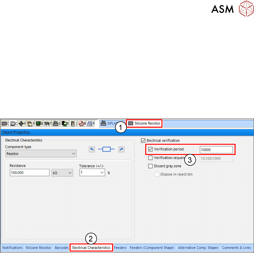
Defining a Verification Period
► Click on the tab(1) of the particular component.
► Click on the Electrical Characteristics tab(2) of the Object Properties view.
► Mark the Verification period check box(3).
► Enter the value in the entry field(3).
4 Operation
4.1 Settings in the Line Software
24 User Manual SIPLACE MeasuringFeeder X 03/2020
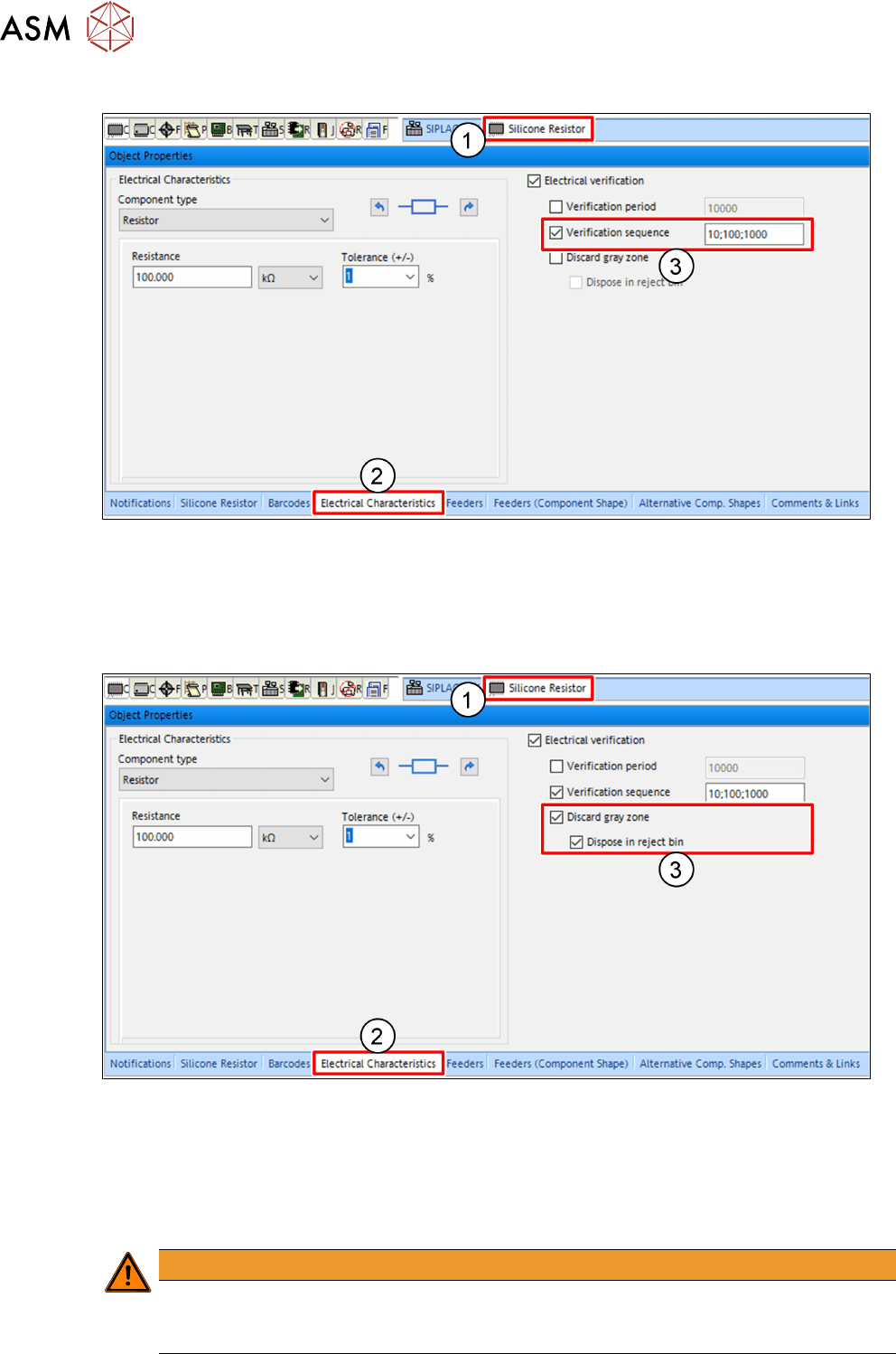
Defining a Verification Sequence
► Click on the tab(1) of the particular component.
► Click on the Electrical Characteristics tab(2) of the Object Properties view.
► Mark the Verification sequence check box(3).
► Enter the values in the entry field(3). The values must be separated by a semicolon.
Defining the Behavior at a Gray Zone
► Click on the tab(1) of the particular component.
► Click on the Electrical Characteristics tab(2) of the Object Properties view.
► Mark the Discard gray zone check box(3).
ð The components in the gray zone are not measured and not placed.
► Mark the Dispose in reject bin check box(3).
ð Every component in the gray zone is picked up and disposed in the reject bin.
WARNING
Danger of Fire
Tantalum capacitors should always be disposed in the reject bin. If they remain in the tape,
they could be hit by the tape cutter and catch fire.
4 Operation
4.1 Settings in the Line Software
User Manual SIPLACE MeasuringFeeder X 03/2020 25
The „Discard gray zone“ check box(3) is cleared.
All components from the Gray Zone are placed. The machine first places the remaining compon-
ents from the old tape and then from the new tape until the estimated "Gray Zone" is completed.
Afterwards a measurement with a component from the new tape is performed.
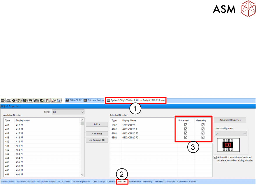
4.1.5 Selecting the Nozzles for Measuring and Placement
For each particular component shape, one or more nozzles must be selected to operate that
component shape. If a component is marked for electrical verification, at least one nozzle must be
selected for measuring:
► Click on the tab(1) of the particular component shape.
► Click on the Nozzles tab(2) of the Object Properties view.
The Selected Nozzles table shows all nozzles that have been selected to operate this particular
component shape.
► For every selected nozzle, mark if it shall be used for placement and / or measuring(3) this
particular component shape.