JO-109-002_JG-0209.pdf - 第113页
4-25 JO-109 1005-001 2.1 Operation Procedure for [Measurement T ype 4] 2.1 Operation Procedure for [Measurement T ype 4] • Lane Original Offset Adjustment, Recognition Mark Position Adjustment and Sprocket Offset Adjustm…
4-24
JO-109
1106-002
2. Feeder Measurement
(22) Detach the master tapes rst, then the tape feeder from the jig.
Now, the measurement is completed.
Note
To measure another feeder (same model) subsequently, follow the
procedures starting with the master tape setting described in (5).
To measure another feeder (different model), follow the procedures
starting with the program change described in (3).
CAUTION
If you detach the tape feeder with the master tapes
being attached from the jig, you may cut your nger
with sharp edges of the master tapes or damage the
tapes by bending the master tapes, etc.
Be sure to detach the master tapes rst, then the
tape feeder from the jig.
Reference
Refer to "2.3 Attachment and Detachment of Master Tapes" in
"Section 4" for how to attach the master tapes.
4-25
JO-109
1005-001
2.1 Operation Procedure for [Measurement Type 4]
2.1 Operation Procedure for [Measurement Type 4]
•
Lane Original Offset Adjustment, Recognition Mark Position
Adjustment and Sprocket Offset Adjustment
This complicated processing is used to perform the lane origin offset
adjustment, recognition mark position adjustment and sprocket offset
adjustment in a single inspection in the case that the feeder feeding section is
disassembled or reassembled, or when it is disassembled to replace the part.
Note
(a) This program performs the same operation contents as in the
adjustment to be performed when the machine is shipped from the
factory.
(b) This inspection type No. is used only for GT/GD-28081 or 28083.
As an example, the operation procedure in the case that the adjustment for
GD-28081 is performed using the [Measurement Type 4], is described.
Procedure
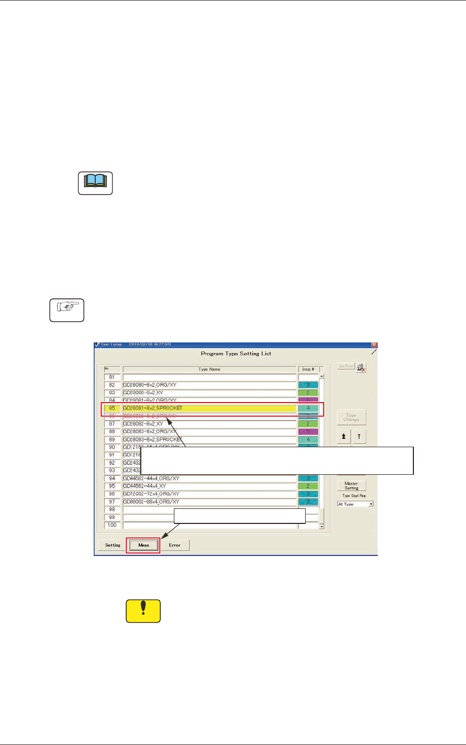
(1) Select the [Measurement Type 4] program for the corresponding
feeder model type, in the program type setup list.
(1) Select the type name “G D28081-8 × 2_SPROCKET”.
( The yellow-highlighted section shows the currently selected program.)
(2) Click the measurement button.
Fig. D27
Notice
Before setup (connect) the feeder to the adjustment
jig, select the program [Measurement Type 4] for the
corresponding feeder model type (manual type change).
When the feeder is setup with the different program
from above selected, the jig recognizes the model type
automatically and type name "GD28081-8 x 2-ORG/XY"
(Measurement Type 5) is selected preferentially.
4-26
JO-109
1005-001
2.1 Operation Procedure for [Measurement Type 4]
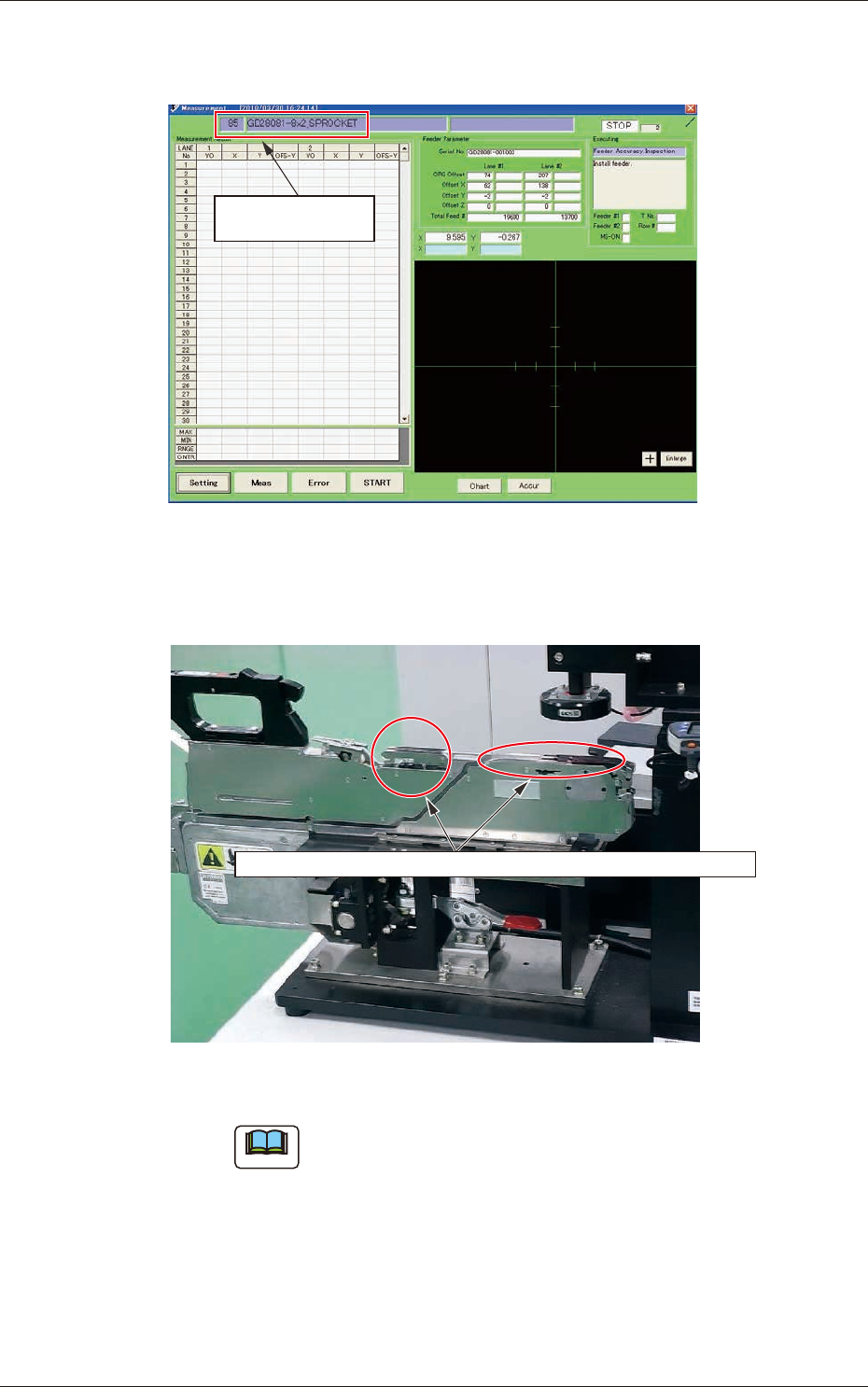
(2) Conrm the program type name displayed in the upper left in the
"Measurement" window.
Confirm the program
type name.
Fig. D28
(3) Connect the feeder to the jig.
When the feeder is to be setup, remove the master tape and light shading jig.
Fig. D29
Note
In the adjustment operation for "Measurement Type 4" or
"Measurement Type 5", rst remove the tape and light shading
jig and then set the feeder.