JO-109-002_JG-0209.pdf - 第41页
2-5 JO-109 1.1 Procedures for Attachment of Camera Unit and Detachment of Fixtures 1005-001 1.1.3 Procedure for Detachment of Fixtures Procedure (1) Detach the xtures for both Y and X axes. Fixture for Y Axis Fixture fo…
2-4
JO-109
1.1 Procedures for Attachment of Camera Unit and Detachment of Fixtures
1005-001
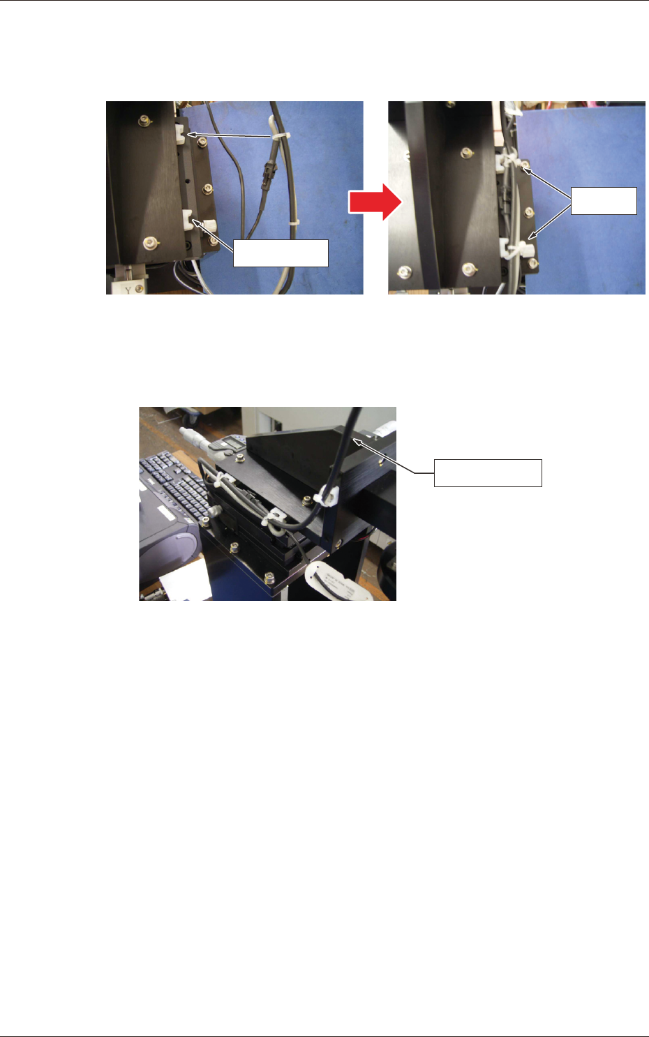
(4) Fasten the cables with tie wraps.
Adjust the tie wraps to the location of the tie mounts and x them
on the tie mounts after tightening the cable ties.
Tie Mount
Bundle
Fig. B5
The cameral cable should also be bundled and xed on the tie
mounts using the tie wraps.
Camera Cable
Fig. B6
2-5
JO-109
1.1 Procedures for Attachment of Camera Unit and Detachment of Fixtures
1005-001
1.1.3 Procedure for Detachment of Fixtures
Procedure
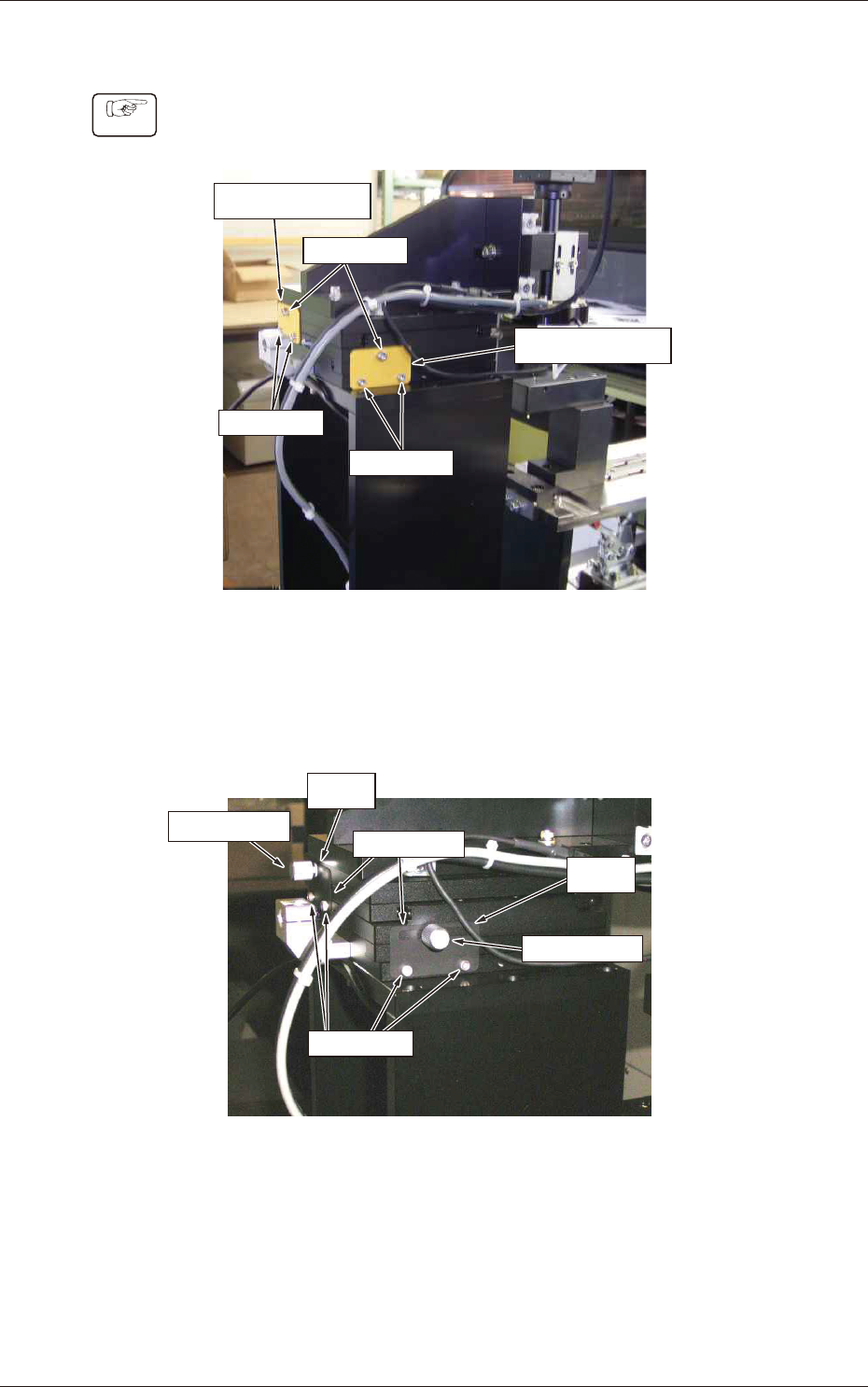
(1) Detach the xtures for both Y and X axes.
Fixture for Y Axis
Fixture for X Axis
Screw (M4)
Screw (M3)
Screw (M3)
Fig. B7
(2) Fix the clamp plate (accessory) with the screws (M3) that were
used to fasten the xtures and tighten the clamp screw for rm
attachment.
X Axis
Y Axis
Clamp Screw
Clamp Screw
Clamp Plate
Screw (M3)
Fig. B8
2-6
JO-109
1.1 Procedures for Attachment of Camera Unit and Detachment of Fixtures
1005-001
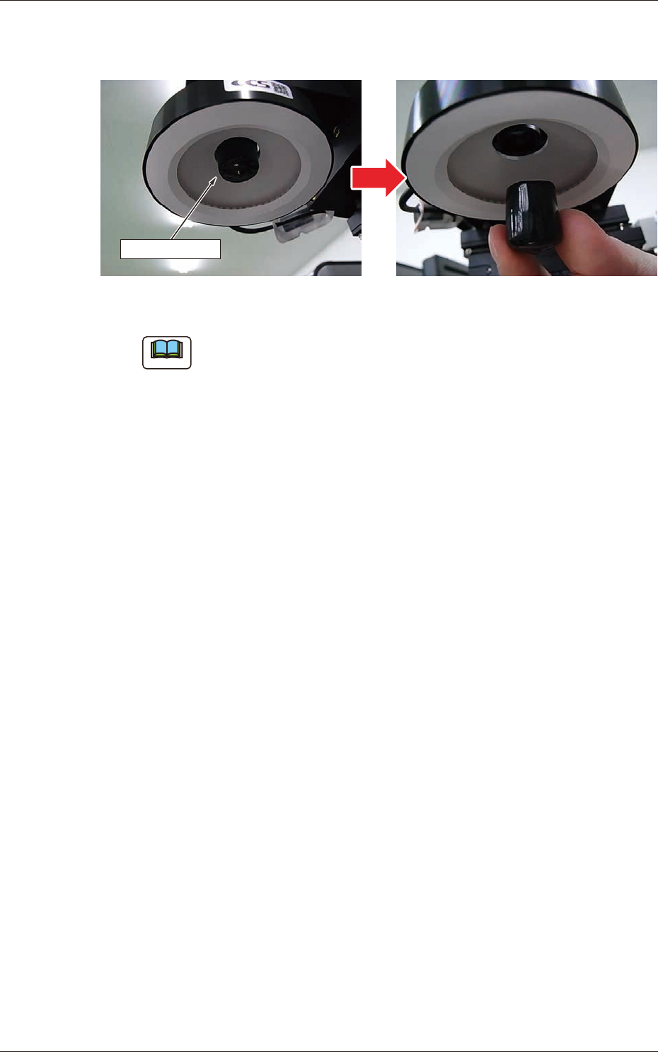
(3) Detach the camera end protection cap located inside the LED
lighting unit.
Protection Cap
Fig. B9
Note
No image can be captured with the protection cap attached.