JO-109-002_JG-0209.pdf - 第46页
2-10 JO-109 1005-001 1.3 Attachment of Micrometer 1.3.1 Replacement of Battery in Micrometer Procedure (1) Put a coin, etc., in the groove of the battery lid and turn it in the A-marked direction (counterclockwise) in th…
2-9
JO-109
1005-001
1.3 Attachment of Micrometer
1.3 Attachment of Micrometer
NOTICE
•
Do not give a strong shock to the micrometer by
hitting against human body or an object.
Otherwise, the micrometer may be damaged,
resulting in inaccurate adjustment of the
component pickup position.
•
Tighten the setscrew until the micrometer can be
moved smoothly.
Excessive tightening may damage the
micrometer.
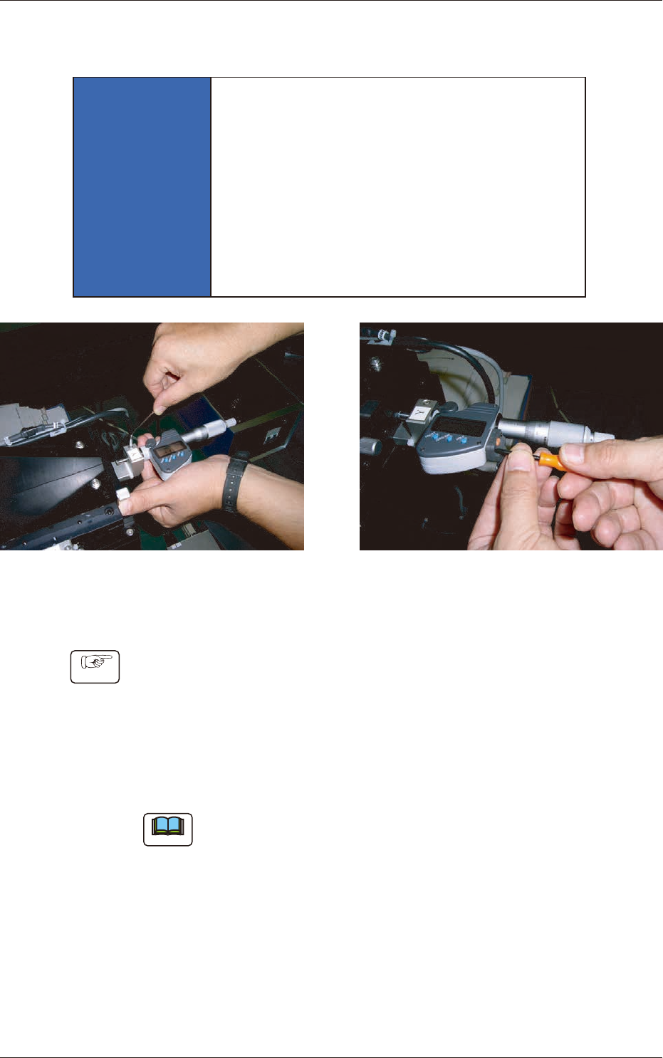
Attachment of Micrometer Connection of Micrometer Cable
Fig. B13 Attachment of Micrometer
Procedure
(1) Attach the micrometer to the measuring jig.
(2) Secure the micrometer with the setscrew.
(3) Connect the cable to the micrometer.
(4) Hold the end of the cable with your ngers and tightn the screw
so that no clearance can be left between the cable and the
micrometer.
Note
After the attachment is completed, check how the micrometer works.
2-10
JO-109
1005-001
1.3 Attachment of Micrometer
1.3.1 Replacement of Battery in Micrometer
Procedure
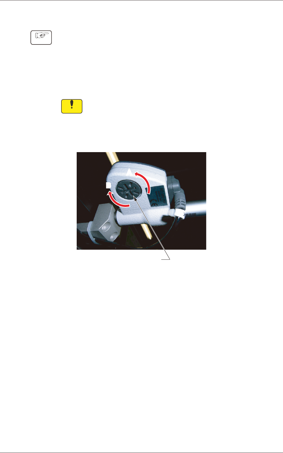
(1) Put a coin, etc., in the groove of the battery lid and turn it in the
A-marked direction (counterclockwise) in the gure below until
the lid comes off.
(2) Take out the old battery.
(3) Put a new battery and set the lid. After that, turn the lid in the
B-marked direction (clockwise) to secure.
Notice
(a) When the battery is reset, the reference position is cleared.
(b) SR44 (Silver Oxide Button Cell Battery) must be used.
(c) When an error display appears or an error message such
as "No Counting" is issued, remove the battery once and
set it back in place.
AA
B
B
Battery Lid
Fig. B14 Back Side of Micrometer
2-11
JO-109
1106-002
2. How to start and end the system
2. How to start and end the system
2.1 Starting the Program
Procedure
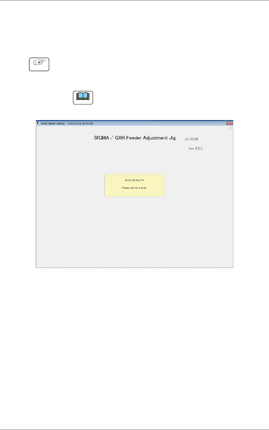
(1) Set the power switch of the electrical box to "ON" and start the
personal computer. The program starts up automatically and the
"Initial Master Setting" window opens.
Note
The displayed name of the feeder adjusting jig is different
from the actual one.
Fig. B15 "Initial Master Setting" Window