JO-109-002_JG-0209.pdf - 第43页
2-7 JO-109 1.2 Cable Connection 1005-001 1.2 Cable Connection Notice Check the seals on the device side and the cable ID plates. Both IDs should match each other when the cables are connected. Seals ID Plates Fig. B10 Fi…
2-6
JO-109
1.1 Procedures for Attachment of Camera Unit and Detachment of Fixtures
1005-001
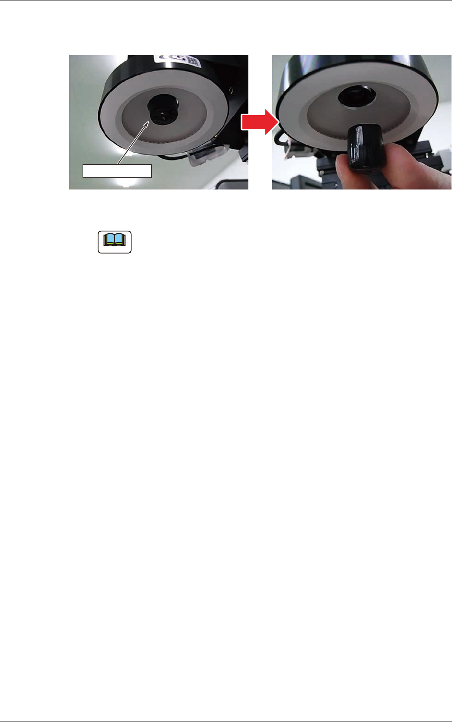
(3) Detach the camera end protection cap located inside the LED
lighting unit.
Protection Cap
Fig. B9
Note
No image can be captured with the protection cap attached.
2-7
JO-109
1.2 Cable Connection
1005-001
1.2 Cable Connection
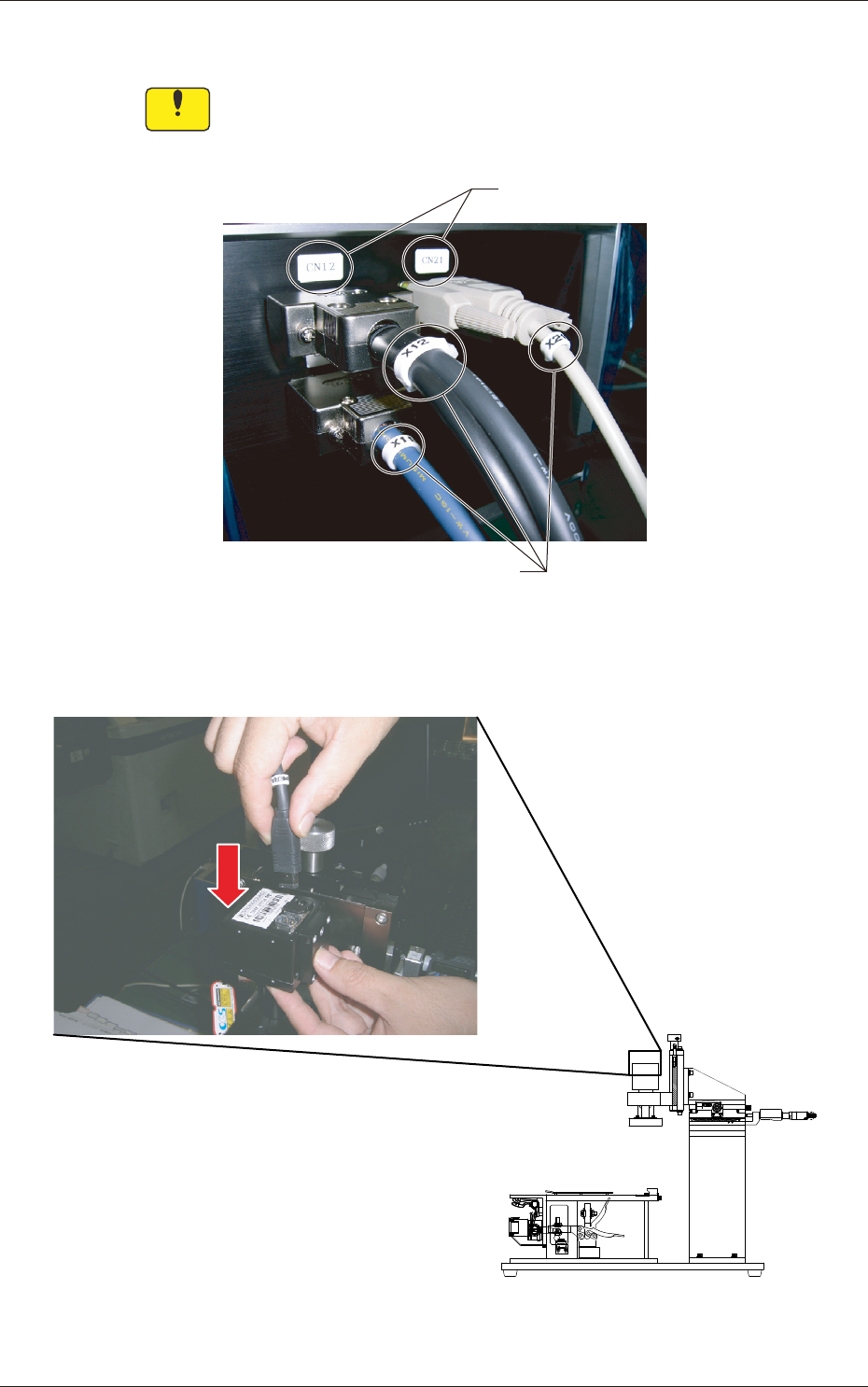
Notice
Check the seals on the device side and the cable ID plates. Both
IDs should match each other when the cables are connected.
Seals
ID Plates
Fig. B10
Fig. B11 Connection of Cables for Camera (used to capture the image of the pickup position)
2-8
JO-109
1005-001
1.2 Cable Connection
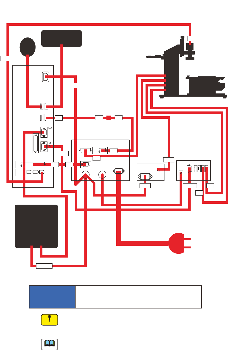
1.2.1 Schematic Cable Distribution
LIGHT
CN12 CN21
CN11
OUT
1 2 3 4
DC 9V
X21
X12
X11
LIGHT
LIGHT
MUX10F
2Y
MUX10F
1X
PC
CAMERA
CAMERA
X23
X22
X22
MONITOR
X13
From 100-240V
Keyboard
Mouse
Personal
Computer
Adjusting Jig
Electrical Box
Micrometer Unit
(Measured Data
Transfer Unit)
Liquid Crystal Display
Power Supply: 100 or 200 V AC
(Note)
Camera Control Unit
(Power Supply for
LED Illumination)
Fig. B12
NOTICE
Check the power source for correct connection
with the specied voltage
Notice
Cable "X23" must be connected only to the specied port of the
personal computer.
It must be connected to the above-indicated port.
Note
An IEC60320 (old IEC320) type power socket can be connected to the
power outlet.