JO-109-002_JG-0209.pdf - 第34页
1-6 JO-109 3. Rough View of Device 1 106-002 3. Rough View of Device *Liquid Crystal Display * : provided by the client. Note (DELL E176FP) Micrometer *Mouse *Keyboard Pickup Position Master T oggle Clamp Measuring Jig A…
1-5
JO-109
2. Specications
1106-002
Table A1-5
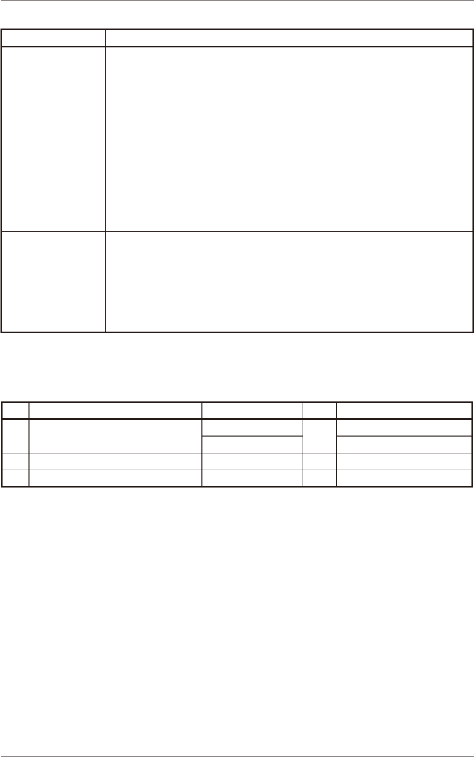
Item Description
10. Dimensions
•
Pickup Position Camera Control Unit (Power Supply for LED Illumination)
76 (Width)
×
154.5 (Depth)
×
55 (Height) mm
•
Micrometer Unit (Measured Data Transfer Unit)
91.4 (Width)
×
92.5 (Depth)
×
50.4 (Height) mm
•
Electrical Box
200 (Width)
×
330 (Depth)
×
160 (Height) mm
•
Measuring Jig
590 (Width)
×
220 (Depth)
×
543.5 (Height) mm
Note
: These are measured without setting the tape feeder and excluding the
micrometer.
11. Mass
•
Pickup Position Camera Control Unit
(Power Supply for LED Illumination) : 0.44 kg
•
Micrometer Unit (Measured Data Transfer Unit) : 0.22 kg
•
Electrical Box : Approx. 4.8 kg
•
Measuring Jig : 25.5 kg
Standard Accessory Parts List
Table A2
No. Product Name Part No. Q'ty Remarks
1 Ferrite Core for Power Cable (2m)
KYD-M804-000
sel.
for 100V
KYF-M86J4-001 for 200V
2 Light Shielding Jig KYD-MD802-000 1
3 Jig Origin Master KYD-M881R-000 1
1-6
JO-109
3. Rough View of Device
1106-002
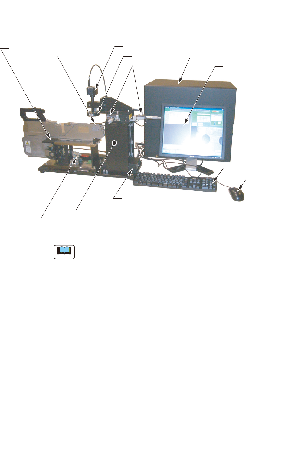
3. Rough View of Device
*Liquid Crystal Display
* : provided by the client.Note
(DELL E176FP)
Micrometer
*Mouse
*Keyboard
Pickup Position
Master
Toggle Clamp
Measuring Jig
Adjustment Base
Pickup Position Camera
*Personal Computer Box
LED Illumination
Micrometer Unit
(Measured Data Transfer Unit)
Fig. A1
Note
The jig in the above inset photo might look different from the actual one.
Personal Computer,
Display, Keyboard, Mouse should be provided by
the client.

2-A
JO-109
1005-001
Section 2
Basic Knowledge
This section describes the procedure for the jig installation
and how to start and end the system.
•
Procedure for Jig Installation
•
How to start and end the system
Section 1 Scopee