JO-109-002_JG-0209.pdf - 第135页
4-47 JO-109 1005-001 3.2 Measuring Method (4) Check the reading of the pry-type dial gauge. Example 1 : When the dial gauge reads "-0.02 mm" as shown below , it is required to enter the of fset value "20&q…
4-46
JO-109
1005-001
3.2 Measuring Method
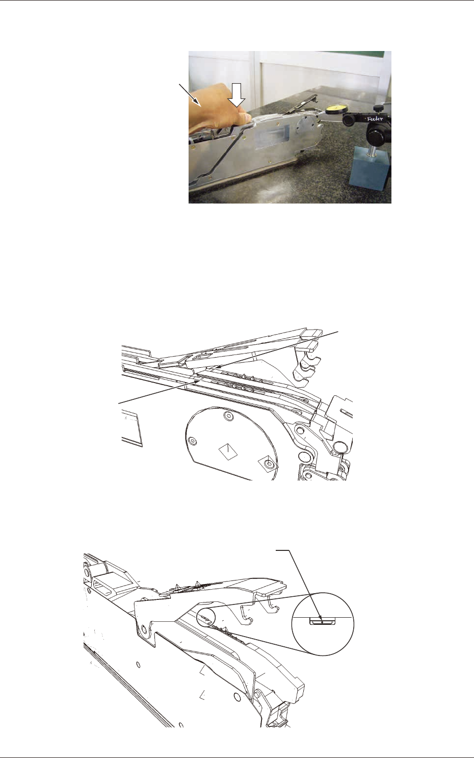
(2) Raise the suppressor and perform the measurement as shown
below.
Measurement with GT-08080 (Example)
Push down the feeder
with your hand.
Fig. D56
(3) See the gures below for the spots to be measured.
•
Measuring Position for G*-0808*
Measuring Position on
Lane #2 Side
Measuring Position on
Lane #1 Side
Fig. D57
•
G*-12160 or more
Measure the area beside
the fiducial mark.
Magnified View
Fig. D58
4-47
JO-109
1005-001
3.2 Measuring Method
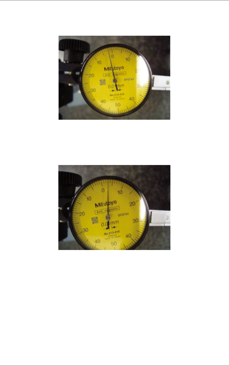
(4) Check the reading of the pry-type dial gauge.
Example 1
: When the dial gauge reads "-0.02 mm" as shown
below, it is required to enter the offset value "20".
Fig. D59
Example 2
: When the dial gauge reads "+0.03 mm" as shown
bellow, it is required to enter the offset value "-30".
Fig. D60

4-48
JO-109
1005-001
4. Default Setting of Program for Feeder Measurement
4. Default Setting of Program for Feeder Measurement
¡
: Measurement Possible with Feeder Adjusting Jig
r
: The data measured by the height gauge can be transferred to the
feeder adjusting jig.
×
: Measurement Impossible
Table D7
Feeder Models GT08080 GT08081
Offset
Name
Lane #1 Origin Offset
¡
×
¡
×
Lane #2 Origin Offset
¡
×
¡
×
Lane #1 Offset X
¡ ¡ ¡ ¡
Lane #1 Offset Y
¡ ¡ ¡ ¡
Lane #1 Offset Z
r r r r
Lane #2 Offset X
¡ ¡ ¡ ¡
Lane #2 Offset Y
¡ ¡ ¡ ¡
Lane #2 Offset Z
r r r r
Required Master Tape Models
JG-0009-12 JG-0009-12 JG-0009-12 JG-0009-12
Program Nos. (Initial Setting Mode)
1 2 3 4
Item
Type Name
GT08080
-8×2_ORG/XY
GT08080
-8×2_XY
GT08081
-8×2_ORG/XY
GT08081
-8×2_XY
Type Name Type ID Nos.
(1 to N)
1 1 1 1
Inspection Type Nos. (1 to 5)
3 2 3 2
# of Sprocket Feeding Times
(1 to 100)
90 90 90 90
Sprocket Feeding Interval
(1 to 100)
9 9 9 9
Sprocket Feeding Delay (ms)
0 0 0 0
# of Components per
Sprocket Circle
90 90 90 90
Component Pitch (mm)
2.000 2.000 2.000 2.000
Lot Data Input Omission
Flag (0 or 1)
1 1 1 1
Fiducial Mark Position X
-3.650 -3.650 -3.650 -3.650
Fiducial Mark Position Y
-13.000 -13.000 -13.000 -13.000
Sprocket Feed Basic
Pitch Y
2.000 2.000 2.000 2.000
# of Divided Pulses for
Origin Offset Adjustment
256 256 256 256
# of Measured Pickup
Holes (1 or 2)
2 2 2 2
Measured Pickup Hole
Position #1 X
0.000 0.000 0.000 0.000
Measured Pickup Hole
Position #1 Y
0.000 0.000 0.000 0.000
Measured Pickup Hole
Position #2 X
9.500 9.500 9.500 9.500
Measured Pickup Hole
Position #2 Y
0.000 0.000 0.000 0.000
Feeder parameter le
(Before measurement)
GT08080-00000A.fdr GT08080-00000A.fdr GT08081-00000A.fdr GT08081-00000A.fdr
Feeder parameter le
(After measurement)
GT08080-00000B.fdr GT08080-00000B.fdr GT08081-00000B.fdr GT08081-00000B.fdr