JO-109-002_JG-0209.pdf - 第133页
4-45 JO-109 1 106-002 3. Measurement of Jig Origin Height 3. Measurement of Jig Origin Height 3.1 Required Measuring Apparatuses • Block Gauge 104.00 mm Ref. : Several block gauges can be piled up to be 104.00 mm. • Pry-…
4-44
JO-109
1005-001
2.4 Attachment and Detachment of Master Tapes (SL)
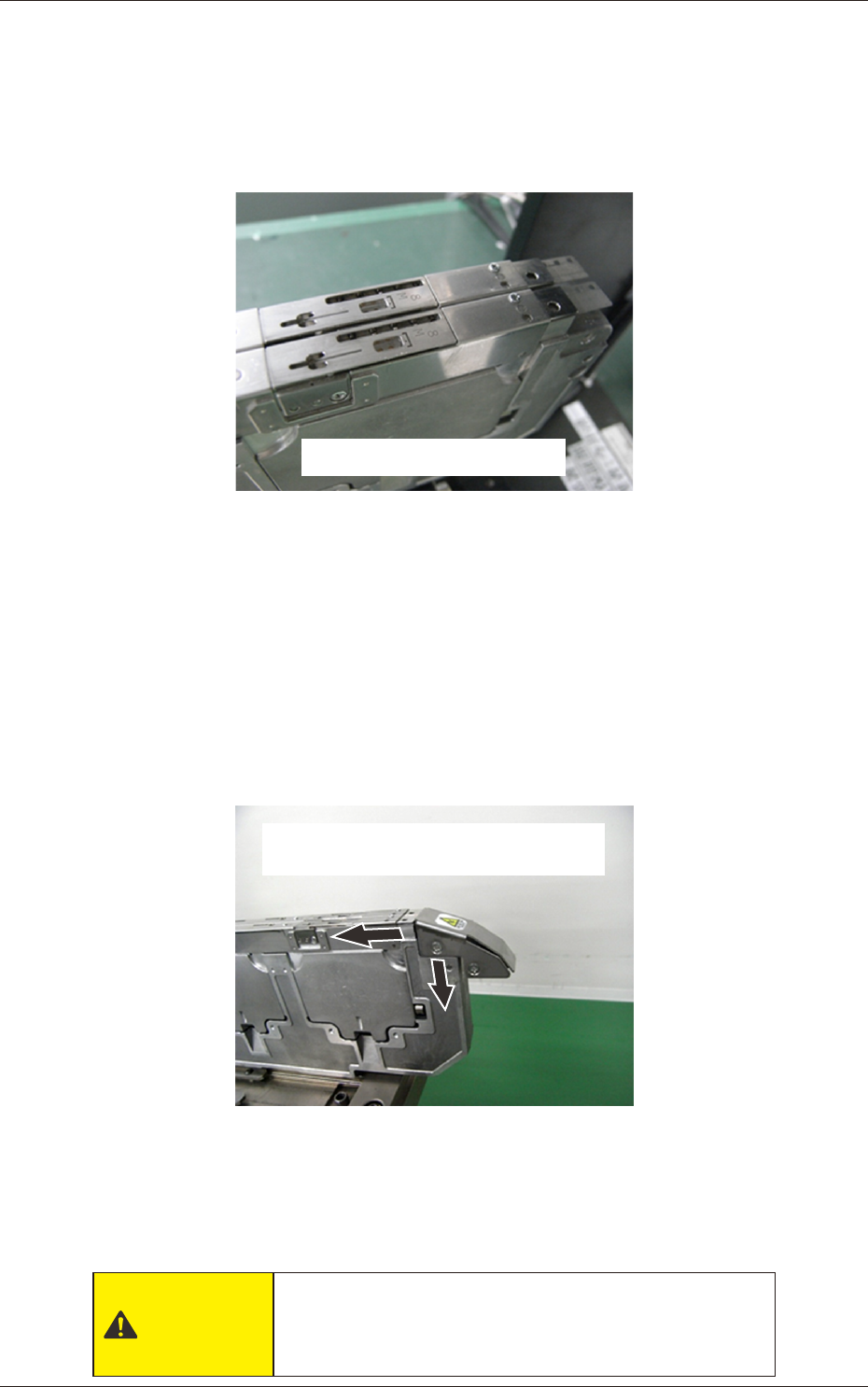
(4) Attach the master tape to the chute section so that the tape feed
holes can be engaged properly with the sprocket pins.
(5) Conrm that no foreign substances (chip components, dirt, dust,
etc.) are scattered on the master tape.
Equipped with Master Tape
Fig D63, SL Feeder Equipped with Master Tapes.
2.4.2 Detachment of Master Tapes (SL)
(1) Pull out the master tape
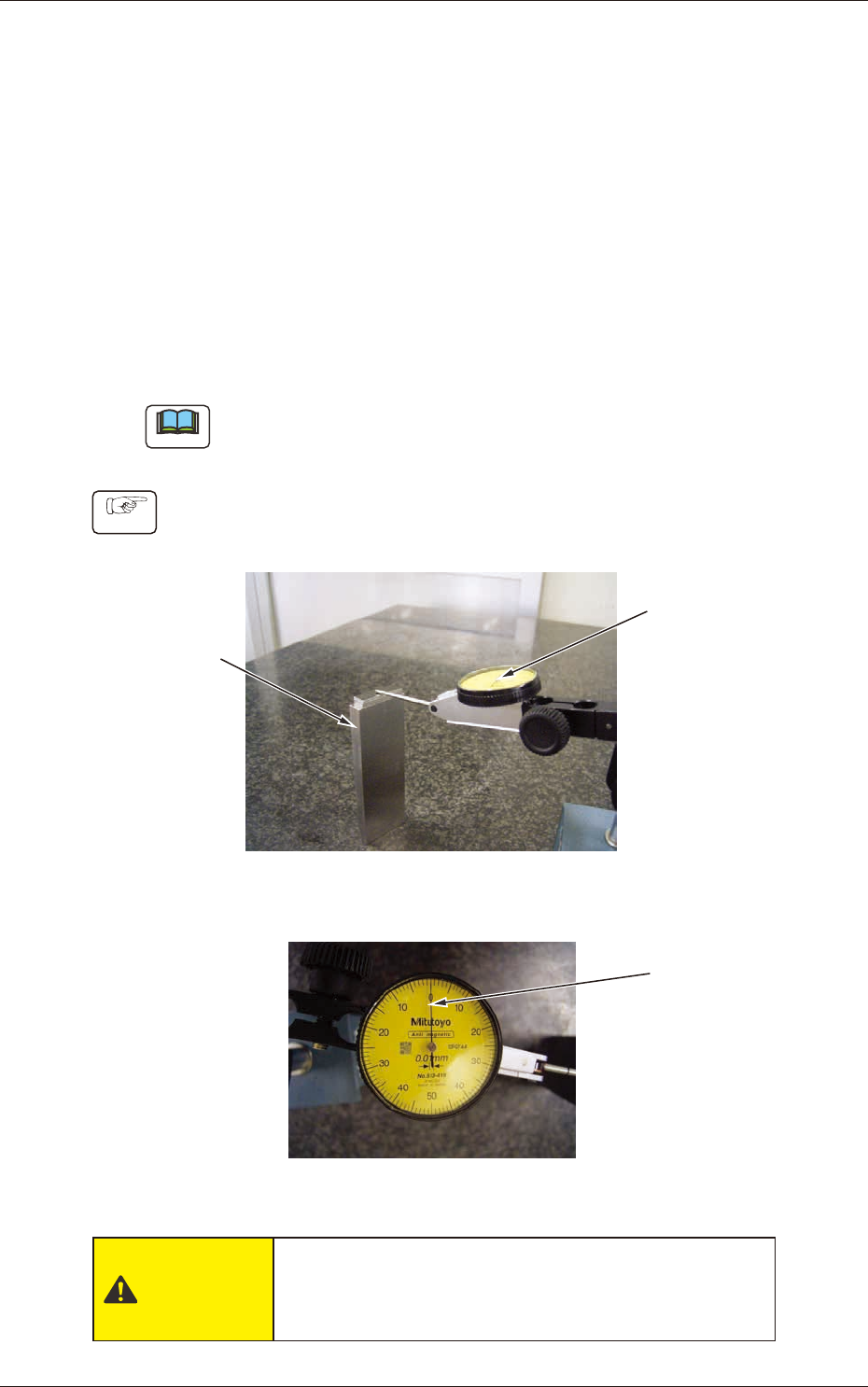
(2) Slowly slide down the suppressor.
(3) Attachment the tape guide
Keep slightly pushing the tape guide to
the feeder frame and attach the tape guide.
Fig. D64
(4) Conrm Slide up to down the suppressor by hand and conrm
that the suppressor moves smoothly.
CAUTION
The master tapes are made of a thin metal. Carefully
handle the tapes to avoid cutting your nger with the
tape edges.
4-45
JO-109
1106-002
3. Measurement of Jig Origin Height
3. Measurement of Jig Origin Height
3.1 Required Measuring Apparatuses
•
Block Gauge 104.00 mm
Ref.
: Several block gauges can be piled up to be 104.00 mm.
•
Pry-Type Dial Gauge 0.01 mm
•
Stand (used for the pry-type dial gauge)
•
Surface Plate Size: 300 mm × 300 mm or more
3.2 Measuring Method
Note
Perform the measurement on the surface plate.
Procedure
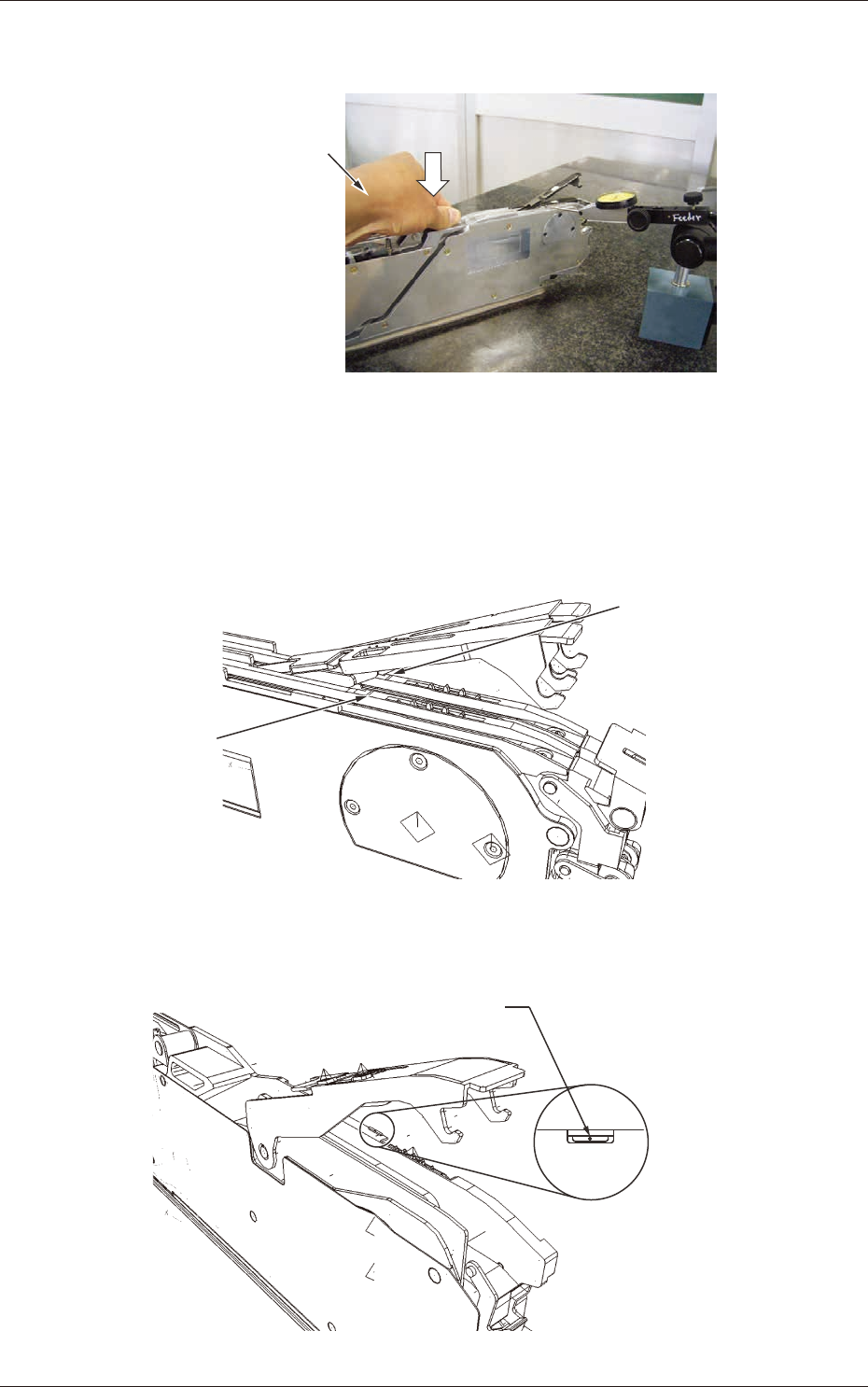
(1) Adjust the pointer of the pry-type dial gauge to "0" (zero), using
the block gauge (104.00).
Block Gauge
104.0 mm
Adjust the pointer
to "0" (zero).
Pry-Type Dial Gauge
Measurement on the surface plate
Fig. D55
CAUTION
Carefully handle the pry-type dial gauge because
the tip of the probe is very sharp. Your hand will get
injured if the tip is inserted.
4-46
JO-109
1005-001
3.2 Measuring Method
(2) Raise the suppressor and perform the measurement as shown
below.
Measurement with GT-08080 (Example)
Push down the feeder
with your hand.
Fig. D56
(3) See the gures below for the spots to be measured.
•
Measuring Position for G*-0808*
Measuring Position on
Lane #2 Side
Measuring Position on
Lane #1 Side
Fig. D57
•
G*-12160 or more
Measure the area beside
the fiducial mark.
Magnified View
Fig. D58