JO-109-002_JG-0209.pdf - 第88页
4-B JO-109 1005-001

4-A
JO-109
1005-001
Section 4
Feeder Measurement
This section describes how to measure the feeders.
•
Registration of Master Position (Jig Origin Adjustment)
•
Feeder Measurement
•
Measurement of Pickup Position Height
•
Default Setting of Program for Feeder Measurement
Section 1 Scopee

4-B
JO-109
1005-001
4-1
JO-109
1. Registration of Master Position
(Jig Origin Adjustment)
Set the power of the electrical box to "ON", turn on the power of the personal
computer, and start up the program for the feeder adjusting jig.
Notice
When the power of the electrical box is turned "OFF" with the power
of the personal computer "ON", the power supplied to the personal
computer is also turned "OFF, causing the personal computer to
break down.
Procedure
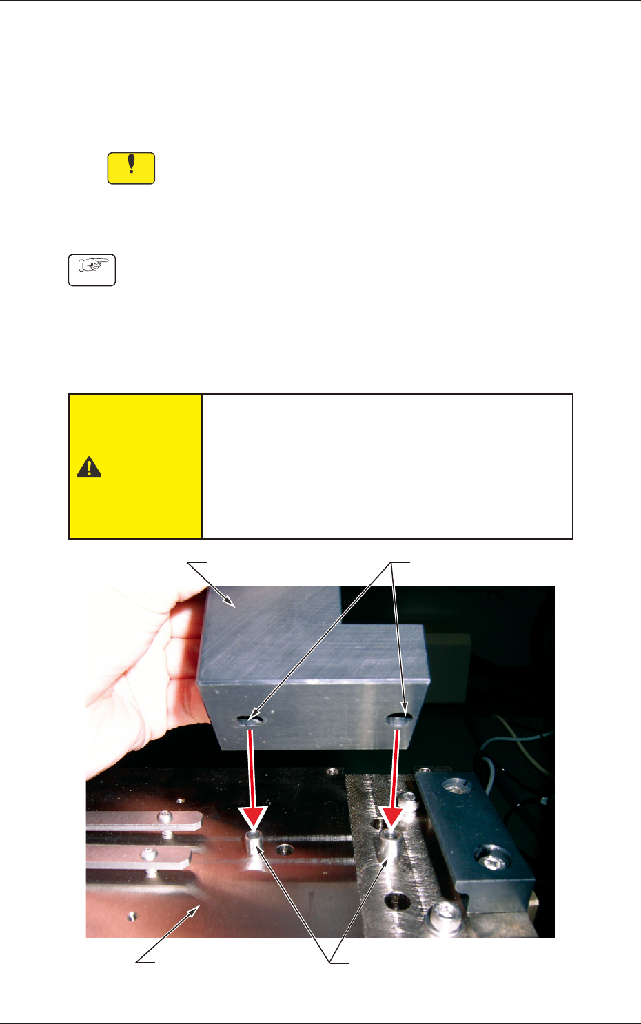
(1) Check to see that no dirt and dust adhere to the mounting face of
the adjustment base and the bottom of the jig origin master. After
the conrmation, set the jig origin master on the jig adjustment
base.
Note that the pins of the adjustment base must be inserted
securely into the holes of the jig origin master.
CAUTION
•
The jig origin master is very heavy. Be sure not to
drop it. Otherwise, your feet will get hurt or the jig
may be damaged.
•
The LED illumination unit uses a Class 2 laser
beam. Do not expose your eyes directly the laser
radiation. Otherwise, your eyes will be injured.
Jig Origin Master
Holes
Adjustment Base
Pins
Fig. D1
1. Registration of Master Position (Jig Origin Adjustment)
1106-002