00196504-02_UM_X-Serie_SR70X_EN.pdf - 第117页
User manual SIPLACE X-series Technical data for the machine From software version SR.70x.xx 01/ 2011 EN edition Dimensions and weight 117 3.3.4.4 Maneuvering dist ance for the component trolley on the X2 machine 3 3 Fig.…
Technical data for the machine User manual SIPLACE X-series
Dimensions and weight From software version SR.70x.xx 01/2011 EN edition
116
3.3.4.3 Maneuvering distance for the component trolley on the X3 machine
3
3
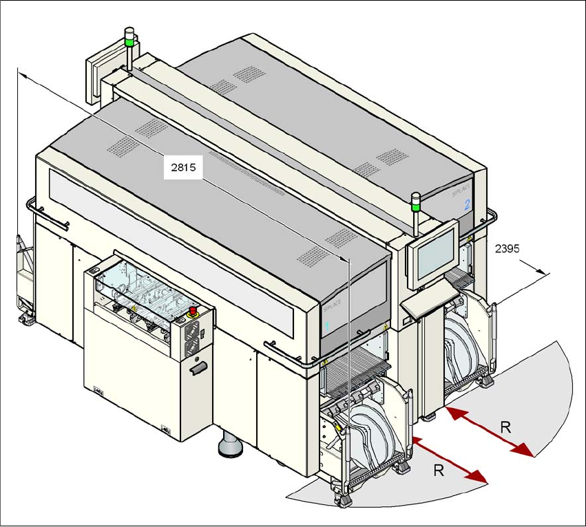
Fig. 3.3 - 8 Maneuvering distance for the component trolley on the X3 machine
The maneuvering distance R of the component trolley on the X3 machine is:
– at locations 1, 3 and 4
750 mm with the handles folded down or
1050 mm with the handles folded up,
– at location 2
600 mm with the handles folded down or
900 mm with the handles folded up.
User manual SIPLACE X-series Technical data for the machine
From software version SR.70x.xx 01/2011 EN edition Dimensions and weight
117
3.3.4.4 Maneuvering distance for the component trolley on the X2 machine
3
3
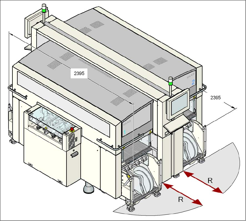
Fig. 3.3 - 9 Maneuvering distance for the component trolley on the X2 machine
The maneuvering distance R of the component trolley on the X2 machine is:
– at locations 2 and 4
600 mm with the handles folded down or
900 mm with the handles folded up
– at location 1 and 3
750 mm with the handles folded down or
1050 mm with the handles folded up.
Technical data for the machine User manual SIPLACE X-series
Dimensions and weight From software version SR.70x.xx 01/2011 EN edition
118
3.3.5 Center of gravity
3
3
3
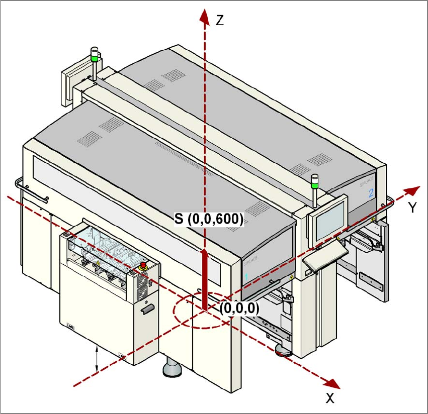
Fig. 3.3 - 10 Center of gravity of the X-series machines in millimeters
3
X coordinate 0 mm
Y coordinate 0 mm
Z coordinate 600 mm high
These center of gravity coordinates relate to placement machines with a PCB conveyor height of
830 mm.