00196504-02_UM_X-Serie_SR70X_EN.pdf - 第210页
Setting up and commissioning User manual SIPLACE X-series Transport and Delivery Configuration From software version SR.70x.xx 01/2011 EN edition 210 4.1.2 Checking a delivery → S tore the machine in the packaging un til…
User manual SIPLACE X-series Setting up and commissioning
From software version SR.70x.xx 01/2011 EN edition Transport and Delivery Configuration
209
4 Setting up and commissioning
4.1 Transport and Delivery Configuration
4.1.1 Shipping packaging
Within Europe, the machine and component trolleys will be shipped on two wooden pallets, pack-
aged in plastic film. Outside Europe, the machine and component trolleys are supplied in wooden
crates.
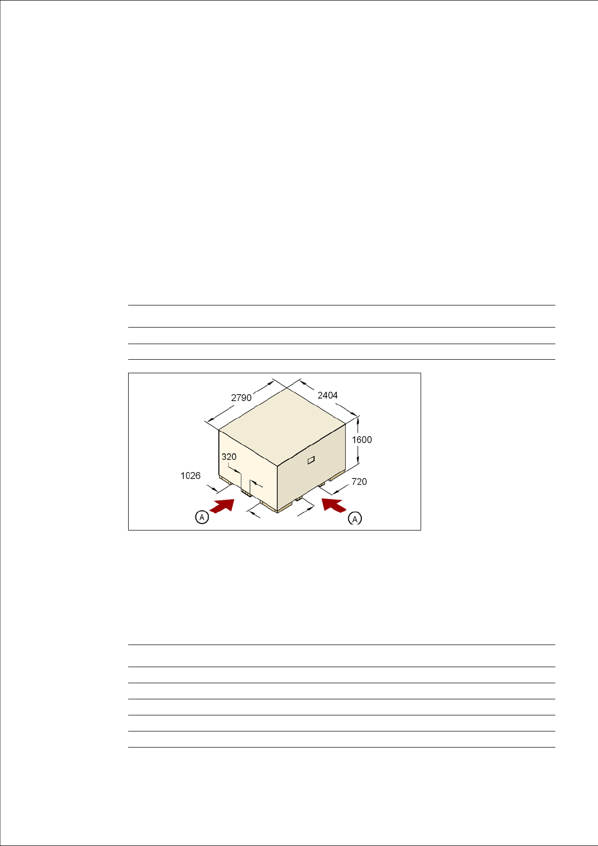
4.1.1.1 Dimensions of the shipping packaging
The dimensions of the pallets and wooden crates are listed in the following table:
4
Fig. 4.1 - 1 Transport crate - dimension in millimeters
(A) Fork-lift attachment points
4.1.1.2 Weight of the machine prepared for dispatch
The following table contains the weights of the machines prepared for dispatch, including packag-
ing.
Machine Component trolley
Pallet 2790 x 2404 mm² 2060 x 1350 mm²
Wooden crate 2790 x 2404 x 1600 mm³ 2060 x 1350 x 1300 mm³
Machine Dispatch within Europe Dispatch overseas
X2 3836 kg 4336 kg
X3 3980 kg 4420 kg
X4 4004 kg 4504 kg
X4I 3859 kg 4359 kg
Component trolley 470 kg 550 kg

Setting up and commissioning User manual SIPLACE X-series
Transport and Delivery Configuration From software version SR.70x.xx 01/2011 EN edition
210
4.1.2 Checking a delivery
→ Store the machine in the packaging until room temperature has been reached. There is oth-
erwise a risk of condensation occurring.
→ Check the delivery for damage.
→ Check the shock sensors.
→ Unpack the machine and the accessories and check the delivery for completeness (reference
delivery note).
→ Document the result in the installation report / acceptance testing report.
4.1.3 Configuration when delivered
The machine is configured as follows when delivered:
– The extension kit on the PCB output side (item 1 in Fig. 4.1 - 2
, page 211) is detached from
the basic machine.
– The axis unit (item 2 in Fig. 4.1 - 2
, page 211) in the extension kit on the PCB output side is
placed on a transport cushion. All cables are attached to the axis unit.
– The track on the single conveyor is set to a width of 210 mm. On the dual conveyor, the width
of conveyor track 1 is 100 mm and of conveyor track 2 is 210 mm. This width setting will be
important when fine-tuning the machine.
On the dual conveyor, the electrical plug-in connectors for the conveyor motor and light bar-
rier on the left-hand conveyor track are easily accessible and there is still enough space to fit
the output conveyor.
– The output conveyors (item 4 in Fig. 4.1 - 2
, page 211) of the single or dual conveyor are dis-
mantled. The electrical cables to the conveyor motors and light barriers are disconnected.
– Both keyboards (item 6 in Fig. 4.1 - 2
, page 211) are unplugged.
– The supporting plates for the keyboards (item 5 in Fig. 4.1 - 2
, page 211) are detached.
– Both monitors (item 7 in Fig. 4.1 - 2
, page 211) are dismantled.
– Both indicator lamps (item 8 in Fig. 4.1 - 2
, page 211) are dismantled.
– All the gantry axes are fixed with shipping braces.
User manual SIPLACE X-series Setting up and commissioning
From software version SR.70x.xx 01/2011 EN edition Transport and Delivery Configuration
211
4
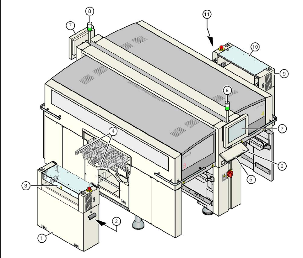
Fig. 4.1 - 2 Machine in the as-delivered configuration
(1) Extension kit on the PCB output side - detached for delivery
(2) Axis unit on the PCB output side - X4I, X4: gantries 2 and 3, X3: gantry 3, X2: gantries 1 and 3
(3) Conveyor cover
(4) Output conveyor
(5) Keyboard supporting plate
(6) Keyboard
(7) Monitor
(8) Indicator lamps
(9) Box PC unit on the PCB input side
(10) Extension kit on the PCB input side - may be removed if necessary
(11) Axis unit on the PCB input side - X4I, X4 and X3: gantries 1 and 4