00196504-02_UM_X-Serie_SR70X_EN.pdf - 第195页
User manual SIPLACE X-series Technical data for the machine From software version SR.70x.xx 01/2011 EN edition X feeder modules 195 W ARNING 3 Please follow the safety instruct ions for processing capacito rs based on po…
Technical data for the machine User manual SIPLACE X-series
X feeder modules From software version SR.70x.xx 01/2011 EN edition
194
3.9.6.1 Technical data
3
3.9.6.2 Number of waffle-pack trays per location and machine
3.9.6.3 Using the waffle-pack tray holder on the X-series component trolley
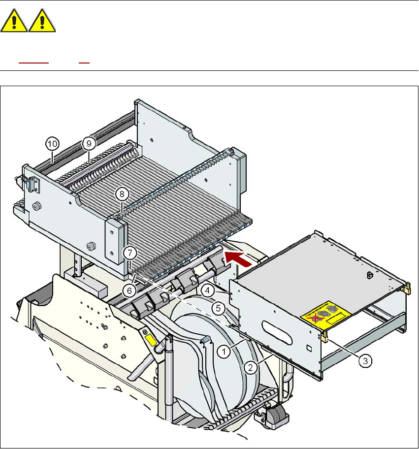
→ Place the two front slider guides (item 1 in Fig. 3.9 - 19, page 195) of the holder on the insertion
aid (item 6 in Fig. 3.9 - 19
, page 195).
→ Push the holder forward along the guide profiles (item 7 in Fig. 3.9 - 19
, page 195). The holder
will slide with its front (item 1) and rear slider guides (item 2 in Fig. 3.9 - 19
, page 195) on the
guide profiles.
→ Carefully push the holder further until the two "front" centering pins (item 4 in Fig. 3.9 - 19
, page
195
) disappear into the centering holes (item 10 in Fig. 3.9 - 19, page 195).
→ Watch the two "back" centering pins (item 3 in Fig. 3.9 - 19
, page 195) on the holder. They must
slide easily into the recesses (item 8 in Fig. 3.9 - 19
, page 195) on the centering bar.
→ When the holder is at the stop position, the locking tabs (item 9 in Fig. 3.9 - 19
, page 195) en-
gage on the locking rollers (item 5) on the holder.
3
The waffle-pack tray holder can be locked and released via the user interface. It is therefore pos-
sible to change the holder while placement is in progress.
Dimensions L x W x H 429 mm x 376 mm x 200 mm
Location filled on the component table 32 locations
a
a) X feeder modules can be positioned at the remaining 8 locations. If locking and retaining rails are used, how-
ever, the fixing lever projecting at the side reduces the available locations to 6.
Positioning option on the X-series machines locations 2 and 4
Software
station software SR.601.xx or later
programming system SIPLACE Pro 3.0 or later
Range of placement heads TwinStar, CPP
Placement machine Location 2 Location 4
X4 1 1
X3 2 1
X2 2 2
User manual SIPLACE X-series Technical data for the machine
From software version SR.70x.xx 01/2011 EN edition X feeder modules
195
WARNING 3
Please follow the safety instructions for processing capacitors based on powdered metal in Sec-
tion 2.6.5.1, page 84.
3
Fig. 3.9 - 19 Inserting a waffle-pack tray holder for the component trolley from the SIPLACE X-series
3
(1) Front slider guide (6) Insertion aid
(2) Back slider guide (7) Slide bar (omega profile)
(3) "Back" centering pin (8) Recess in the centering bar for holding the
"back" centering pin
(4) "Front" centering pin (9) Locking latches
(5) Locking roller (10) Centering holes on the component table for
holding the "front" centering pin
Technical data for the machine User manual SIPLACE X-series
SIPLACE X-series component trolley From software version SR.70x.xx 01/2011 EN edition
196
3.10 SIPLACE X-series component trolley
Item no. 00119722-xx CO trolley SIPLACE X-series
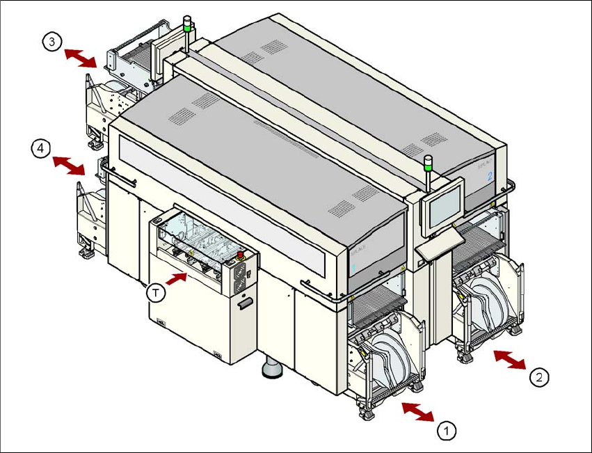
Up to four SIPLACE X-series component trolleys can be docked into the machines from the
SIPLACE X-series. The locations are numbered as shown in the diagram below.
3
Fig. 3.10 - 1 Component trolley locations, SIPLACE X-series
(1) Location 1
(2) Location 2
(3) Location 3
(4) Location 4
(T) PCB direction of travel
The component trolleys are stand-alone modules that can be set up with feeders at an external
set-up area. This means that the production process only has to be interrupted briefly in order to
change the component trolley.