00196504-02_UM_X-Serie_SR70X_EN.pdf - 第284页
Setting up and commissioning User manual SIPLACE X-series Adapting the component trolley to the PCB conveyor height From software version SR.70x.xx 01/2011 EN edition 284 4.4.1 W arning instructions WA R N IN G 4 Only AS…
User manual SIPLACE X-series Setting up and commissioning
From software version SR.70x.xx 01/2011 EN edition Adapting the component trolley to the PCB conveyor height
283
4.4 Adapting the component trolley to the PCB con-
veyor height
The component trolley for the X feeder modules can be set to the following PCB conveyor heights
with just a few simple actions:
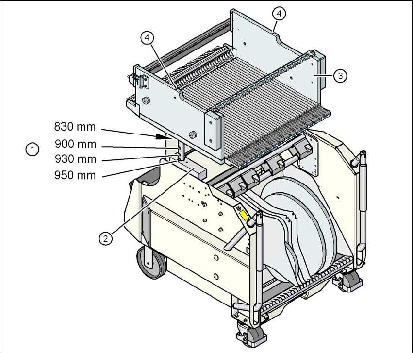
830 mm ± 15 mm
900 mm ± 15 mm
930 mm ± 15 mm (standard height)
950 mm ± 15 mm (SMEMA height) 4
4
Fig. 4.4 - 1 Component trolley (SIPLACE X-series) with a PCB conveyor height of 950 mm
(1) Holes in the guide columns for the transport heights of 900, 930 and 950 mm.
If the transport height is 830 mm, the component table lies on the block (2).
(2) Block
(3) Component table
(4) M8 holes for fixing the mounting device
Setting up and commissioning User manual SIPLACE X-series
Adapting the component trolley to the PCB conveyor height From software version SR.70x.xx 01/2011 EN edition
284
4.4.1 Warning instructions
WARNING 4
Only ASM AS engineers or qualified personnel are permitted to adjust the component trolley
height.
→ Always follow the applicable accident prevention regulations.
→ Remove all the feeder modules from the component table, if you want to adjust the height for
the component table.
4.4.2 Tools and equipment
You will need the following tools and equipment to adjust the height of the component trolley:
–Hammer
– Punch, 8 mm
– Mounting device (item no. 03015976-xx)
– Lifting device for raising the component trolley table, carrying capacity at least 80 kg
4.4.3 Changing the component trolley height
WARNING 4
→ Remove all the feeder modules from the component table.
→ Fit the mounting device to the component table in order to adjust the height. This prevents
the component table becoming deformed when the table is raised or lowered.
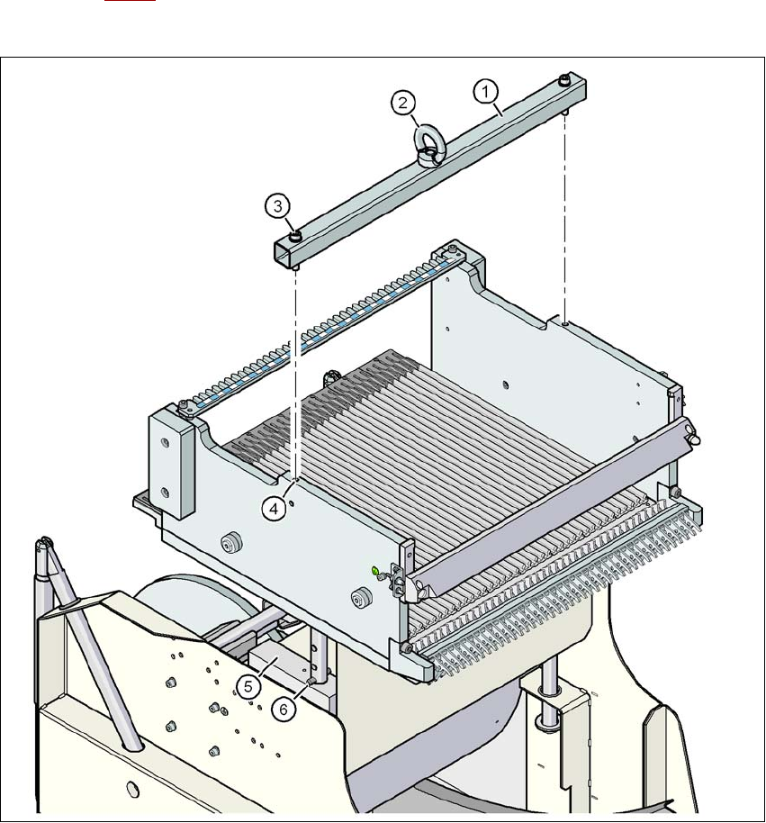
→ Fix the assembly guide (item 1 in Fig. 4.4 - 2
, page 285) using the two hexagon socket head
screws M8 x 50 (item 3 in Fig. 4.4 - 2
, page 285) to the component table (item 4 in Fig. 4.4 -
2, page 285).
→ Attach the hooks of the lifting device to the eyelet (item 2 in Fig. 4.4 - 2
, page 285).
→ Raise the component trolley bed slightly to expose the split pins (item 6 in Fig. 4.4 - 2
, page
285
).
→ Use the punch to carefully tap out the split pins on both sides.
→ Insert the spiral clamping pins into the holes for the required PCB conveyor height (see Fig.
4.4 - 1
, page 283).
User manual SIPLACE X-series Setting up and commissioning
From software version SR.70x.xx 01/2011 EN edition Adapting the component trolley to the PCB conveyor height
285
→ Lower the component trolley bed slowly until the split pins lie on the supporting blocks (item
5 in Fig. 4.4 - 2
).
→ Dismantle the mounting device.
4
Fig. 4.4 - 2 Fixing the assembly guide to the component table of the SIPLACE X component trolley
(1) Mounting device
(2) Eyelet
(3) Hexagon socket head screw DIN 912, M8 x 50, 2 x
(4) M8 threaded hole in the component table, 2x
(5) Supporting block, 2x
(6) Split pin, DIN 7343, 8 x 40 - St, 2 x