00196504-02_UM_X-Serie_SR70X_EN.pdf - 第387页
User manual SIPLACE X-series Station extensions From software version SR.70x.xx 01/2011 EN edition Dock ing station for the SIPLACE X-series CO tr olley 387 6.2.4 Controls and displays 6 Fig. 6.2 - 4 Docking station - Co…
Station extensions User manual SIPLACE X-series
Docking station for the SIPLACE X-series CO trolley From software version SR.70x.xx 01/2011 EN edition
386
6
6
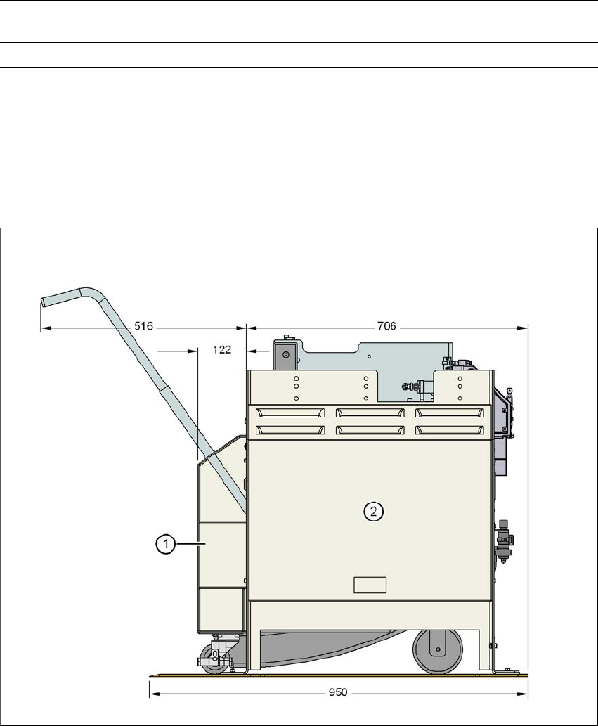
6.2.3 Dimensions for the docking station with component trolley docked
6
Fig. 6.2 - 3 Docking station with component trolley docked - dimensions in millimeters
(1) CO trolley
(2) Docking station
Rated current 3.5 A (230 VAC)
7 A (115 VAC)
Nominal apparent power 0.8 kW
Fuse protection 2 x 8 A
a) Under normal atmospheric conditions at 20°C and 1013 hPa
User manual SIPLACE X-series Station extensions
From software version SR.70x.xx 01/2011 EN edition Docking station for the SIPLACE X-series CO trolley
387
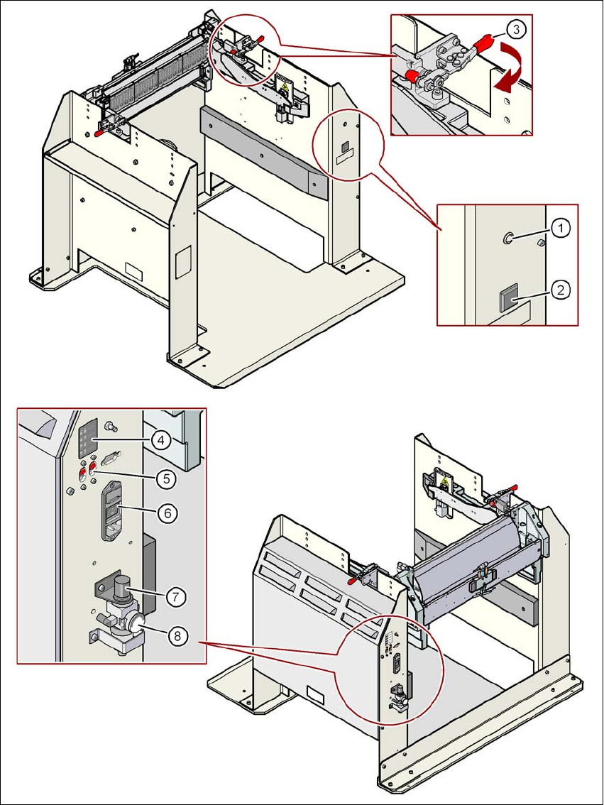
6.2.4 Controls and displays
6
Fig. 6.2 - 4 Docking station - Controls and displays

Station extensions User manual SIPLACE X-series
Docking station for the SIPLACE X-series CO trolley From software version SR.70x.xx 01/2011 EN edition
388
Key to fig. 6.2 - 4
, page 387.
(1) Main power supply indicator lamp
(2) Button for locking and releasing all the feeder modules on the component trolley
(3) Horizontal tensioner for fixing the component table lever in the "closed" position
(4) Label showing switches S1 and S2 for CAN bus addressing
(5) Switches S1 and S2 for setting the CAN bus address
(6) Power switch
(7) Rotary knob for setting the operating pressure
(8) Manometer for displaying the operating pressure