00196504-02_UM_X-Serie_SR70X_EN.pdf - 第418页
Station extensions User manual SIPLACE X-series PCB alignment From software version SR.70x.xx 01/2011 EN edition 418 6.1 1 PCB alignment Item no. 00 1 19677- xx PCB alignme nt, single conv eyor , SIPLAC E HF/X/D3 (not f …

User manual SIPLACE X-series Station extensions
From software version SR.70x.xx 01/2011 EN edition PCB barcode scanner
417
1D code types UPC, EAN, Codabar 2/5 Interleaved, Code 39, Code
128, Code 99
2D code types Data Matrix ECC 200
Station extensions User manual SIPLACE X-series
PCB alignment From software version SR.70x.xx 01/2011 EN edition
418
6.11 PCB alignment
Item no. 00119677-xx PCB alignment, single conveyor, SIPLACE HF/X/D3 (not for X4I)
Item no. 00119678-xx PCB alignment, dual conveyor, SIPLACE HF/X/D3 (not for X4I)
6.11.1 Description
PCBs to be processed sometimes have a length to width ratio of 1:2 or worse. This means that
the shorter side of the PCB points in the direction of travel. During travel, such PCBs may twist
slightly and, as a result, the fiducials no longer lie within the PCB vision camera's search window.
In this case, the "PCB alignment" option ensures that these PCBs are realigned precisely at the
stopping position.
If PCBs with recesses in the direction of travel are processed, this may result in different process-
ing positions on machines with mechanical stoppers (HS-50, S-25 HM, F5 HM) and on machines
that monitor this position with laser light barriers (X-series, HF-series, HS-60, S-27 HM). The "PCB
alignment" option ensures that the PCBs are stopped at the same position on all PCB conveyors.
The "PCB alignment" option is available for both single and dual conveyors.
6
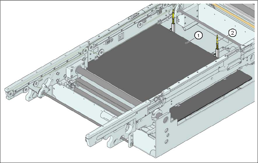
Fig. 6.11 - 1 PCB alignment
(1) Lifting table
(2) PCB stop
User manual SIPLACE X-series Station extensions
From software version SR.70x.xx 01/2011 EN edition Siemens interface
419
The PCB is transported into the placement area until the laser light barrier triggers the stop signal
for the PCB conveyor. The lifting table with the PCB stops then moves up into a position in which
the PCB is not yet clamped and can still be moved by the conveyor belts. The two PCB stops are
level with the PCB, and the PCB supports (magnetic pins) are already in contact with the PCB.
The two conveyor belts move the PCB against the PCB stops and align them at the same time.
The lifting table then moves into its top end position, clamps the PCB and releases it from the PCB
stops so as not to affect the placement process. After the placement process, the lifting table and
PCB alignment are lowered and the PCB is moved on.
6
6.12 Siemens interface
Item no. 00116808-xx SIPLACE interface HF/X/D3
The conveyor interface on the placement machines from the X-series is configured to the SMEMA
standard. It is, however, still possible to use this interface in accordance with the Siemens stan-
dard. This is a significant benefit when an X-series machine is to be integrated into older SIPLACE
lines, in which case it would not be necessary to retrofit the older machines to conform to the
SMEMA standard.
Simply configure the conveyor interface of the X-series machines to the Siemens standard and
connect the machines using the associated interface cable.
More detailed information can be found in the Siemens conveyor interface retrofit instructions",
item no. 00194343-01.