00196504-02_UM_X-Serie_SR70X_EN.pdf - 第388页
Station extensions User manual SIPLACE X-series Docking station for the SIPLACE X-ser ies CO trol ley From software version SR.70x.xx 01/2011 EN edition 388 Key to fig. 6.2 - 4 , p age 387 . (1) Main power supply ind ica…
User manual SIPLACE X-series Station extensions
From software version SR.70x.xx 01/2011 EN edition Docking station for the SIPLACE X-series CO trolley
387
6.2.4 Controls and displays
6
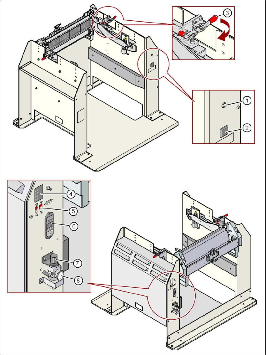
Fig. 6.2 - 4 Docking station - Controls and displays

Station extensions User manual SIPLACE X-series
Docking station for the SIPLACE X-series CO trolley From software version SR.70x.xx 01/2011 EN edition
388
Key to fig. 6.2 - 4
, page 387.
(1) Main power supply indicator lamp
(2) Button for locking and releasing all the feeder modules on the component trolley
(3) Horizontal tensioner for fixing the component table lever in the "closed" position
(4) Label showing switches S1 and S2 for CAN bus addressing
(5) Switches S1 and S2 for setting the CAN bus address
(6) Power switch
(7) Rotary knob for setting the operating pressure
(8) Manometer for displaying the operating pressure
User manual SIPLACE X-series Station extensions
From software version SR.70x.xx 01/2011 EN edition Docking station for the SIPLACE X-series CO trolley
389
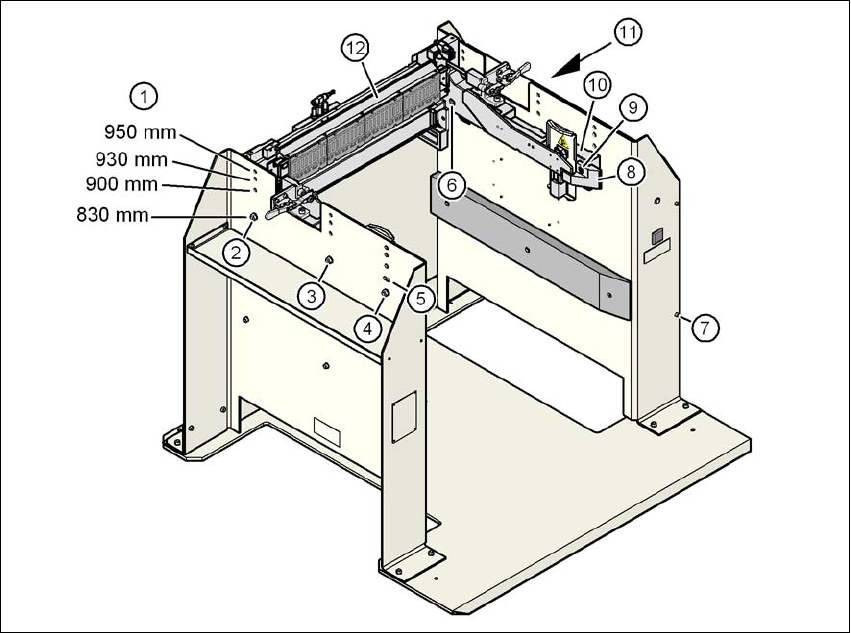
6.2.5 Adapting the docking station to the PCB conveyor height
The component trolley docking unit can be adjusted to PCB conveyor heights of 830 mm, 900 mm,
930 mm and 950 mm in just a few simple actions.
6
Fig. 6.2 - 5 Adapting the component trolley docking unit to the PCB conveyor heights
(1) Holes for the PCB conveyor height
(2) Hexagonal nut M8 and washer, 2x
(3) Hexagonal nut M8 and washer, 2x
(4) Hexagonal nut M8 and washer, 2x
(5) Slot for height adjustment
(6) Hexagon socket head screw M8x40, 6x
(7) Hexagon socket head screw M5x12, 4x
(8) Guide
(9) Hexagon socket head screw M8x18, 2x
(10) Side section, component trolley docking unit
(11) Paneling on the docking station
(12) Feeder module control unit (FCU)