00196504-02_UM_X-Serie_SR70X_EN.pdf - 第282页
Setting up and commissioning User manual SIPLACE X-series Setting up the machine From software version SR.70x.xx 01/2011 EN edition 282 4.3.20 Removing the corrosion pr otection from the guide rails The machines we re gi…
User manual SIPLACE X-series Setting up and commissioning
From software version SR.70x.xx 01/2011 EN edition Setting up the machine
281
→ Make sure that you do not unscrew the middle machine feet so far that the machine is no lon-
ger adjusted.
4
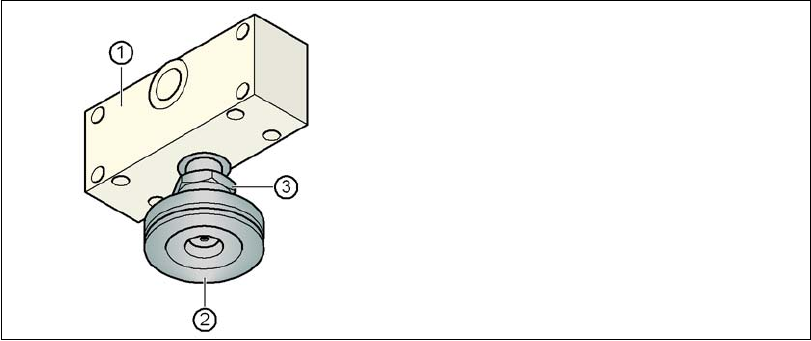
Fig. 4.3 - 33 Aligning and locking the middle machine foot
→ Use the spirit level to ensure that the machine is precisely aligned.
→ Use the size 65 open-ended spanner to tighten the M24 lock nut (item 3).
4.3.19 Removing the shipping braces
– Remove all the shipping braces from the gantry axes.
(1) Spacer
(2) Middle machine foot
(3) M24 lock nut
Setting up and commissioning User manual SIPLACE X-series
Setting up the machine From software version SR.70x.xx 01/2011 EN edition
282
4.3.20 Removing the corrosion protection from the guide rails
The machines were given a corrosion protection treatment before they were delivered.
CAUTION 4
– You should therefore remove the corrosion protection from all the axes and bearings when
you traverse the machine axes for the first time during commissioning.
– Grease all the axes and bearings with the grease described in the maintenance instructions.
If the corrosion protection agent is mixed with the bearing grease on the axes this can greatly re-
duce the service life of the bearings and guide rails.
CAUTION 4
Do not allow any alcohol to enter the guide carriages when you clean the guide rails and scale
rods. Alcohol will damage the bearing grease in the guide carriages.
User manual SIPLACE X-series Setting up and commissioning
From software version SR.70x.xx 01/2011 EN edition Adapting the component trolley to the PCB conveyor height
283
4.4 Adapting the component trolley to the PCB con-
veyor height
The component trolley for the X feeder modules can be set to the following PCB conveyor heights
with just a few simple actions:
830 mm ± 15 mm
900 mm ± 15 mm
930 mm ± 15 mm (standard height)
950 mm ± 15 mm (SMEMA height) 4
4
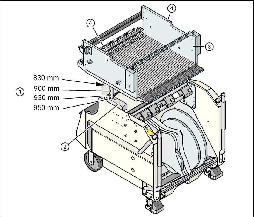
Fig. 4.4 - 1 Component trolley (SIPLACE X-series) with a PCB conveyor height of 950 mm
(1) Holes in the guide columns for the transport heights of 900, 930 and 950 mm.
If the transport height is 830 mm, the component table lies on the block (2).
(2) Block
(3) Component table
(4) M8 holes for fixing the mounting device