00196504-02_UM_X-Serie_SR70X_EN.pdf - 第215页
User manual SIPLACE X-series Setting up and commissioning From software version SR.70x.xx 01/2011 EN edition Transport and Delivery Configur ation 215 4 Fig. 4.1 - 3 Contact surfaces - Forks parallel to the direction of …
Setting up and commissioning User manual SIPLACE X-series
Transport and Delivery Configuration From software version SR.70x.xx 01/2011 EN edition
214
4.1.5.3 Points for attaching the fork-lift on the machine
The next two diagrams show the fork-lift attachment points on the machine if you want to lift the
machine from the pallet or transport it without a pallet.
PLEASE NOTE 4
Always use a pallet and fork-lift to transport the machine over longer distances in order to avoid
damaging the machine.
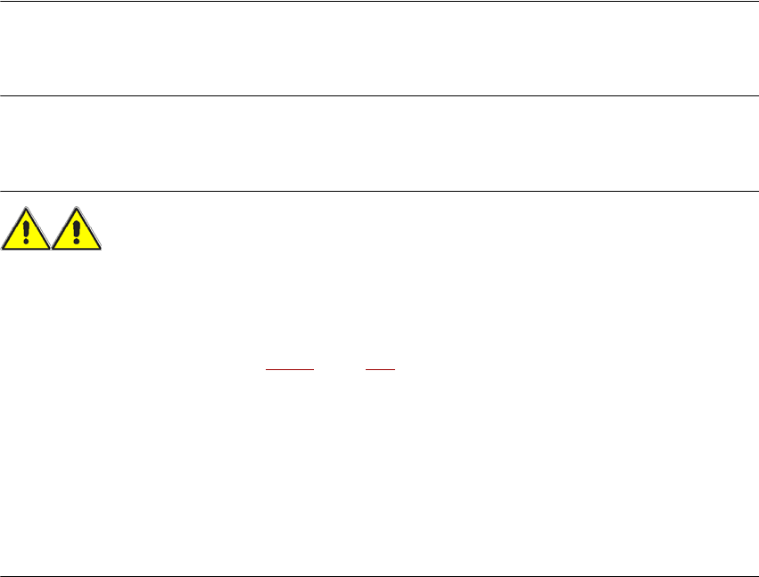
Forks parallel to the PCB conveyor 4
WARNING 4
Please note the following points before you raise the machine in order to avoid irreversible dam-
age to the machine:
– Open the forks just wide enough to position them between the two machine feet (the attach-
ment points are shown in Fig. 4.1 - 3
, page 215). The machine feet are 776 mm apart. NEVER
increase the distance between the forks so that the machine is lifted on the side parts of the
machine frame, since this would deform the machine frame.
→ Make sure that the forks are evenly loaded when you lift the machine. A firm support between
the forks and machine will prevent the machine tilting when it is raised. This will also prevent
a one-sided load on the machine feet, which would deform the fixing of the machine feet. We
recommend that a second person watch the machine as it is raised, and make sure that the
machine does not tip to one side when lifted with the fork-lift.
User manual SIPLACE X-series Setting up and commissioning
From software version SR.70x.xx 01/2011 EN edition Transport and Delivery Configuration
215
4
Fig. 4.1 - 3 Contact surfaces - Forks parallel to the direction of PCB transport
(1) Contact surfaces for the forks of the fork-lift
Setting up and commissioning User manual SIPLACE X-series
Transport and Delivery Configuration From software version SR.70x.xx 01/2011 EN edition
216
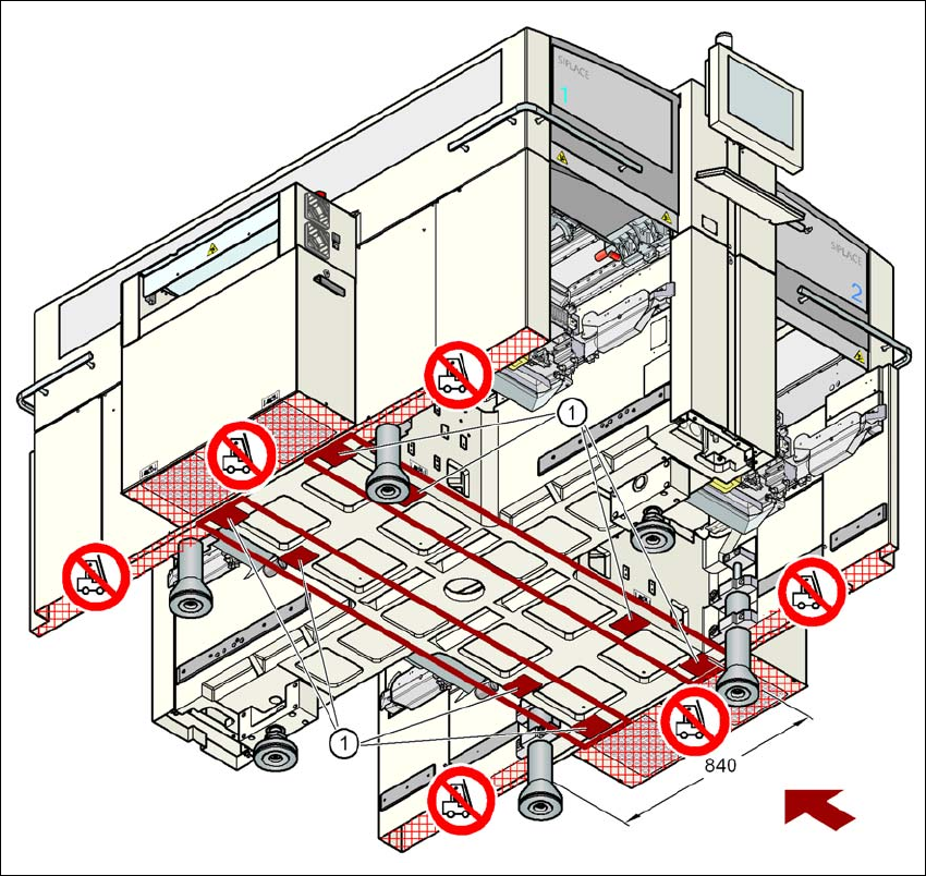
Forks across the PCB conveyor 4
4
Fig. 4.1 - 4 Contact surfaces - Forks across the direction of PCB transport
(1) Contact surfaces for the forks of the fork-lift
WARNING 4
Please note the following points before you raise the machine in order to avoid irreversible dam-
age to the machine:
– The distance between the forks must be between 800 and 900 mm. The attachment surfaces
for the fork-lift are shown in Fig. 4.1 - 4
. The maximum distance between the contact surfaces
is 1120 mm. NEVER increase the distance between the forks so that the machine is lifted on
the side parts of the machine frame, since this would deform the machine frame.