00196504-02_UM_X-Serie_SR70X_EN.pdf - 第286页
Setting up and commissioning User manual SIPLACE X-series Adapting the used tape chute to the PCB conveyor he ight From software version SR.70x.xx 01/2011 EN edition 286 4.5 A dapting the used t ape chute to the PCB conv…
User manual SIPLACE X-series Setting up and commissioning
From software version SR.70x.xx 01/2011 EN edition Adapting the component trolley to the PCB conveyor height
285
→ Lower the component trolley bed slowly until the split pins lie on the supporting blocks (item
5 in Fig. 4.4 - 2
).
→ Dismantle the mounting device.
4
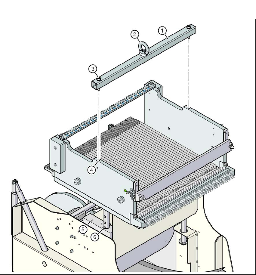
Fig. 4.4 - 2 Fixing the assembly guide to the component table of the SIPLACE X component trolley
(1) Mounting device
(2) Eyelet
(3) Hexagon socket head screw DIN 912, M8 x 50, 2 x
(4) M8 threaded hole in the component table, 2x
(5) Supporting block, 2x
(6) Split pin, DIN 7343, 8 x 40 - St, 2 x
Setting up and commissioning User manual SIPLACE X-series
Adapting the used tape chute to the PCB conveyor height From software version SR.70x.xx 01/2011 EN edition
286
4.5 Adapting the used tape chute to the PCB conveyor
height
4.5.1 Adapting the used tape chute to the PCB -conveyor height
Depending on the PCB conveyor height, the length of the waste tape chute can be set so that the
pieces of tape are diverted directly into the waste tape container of the component trolley.
4
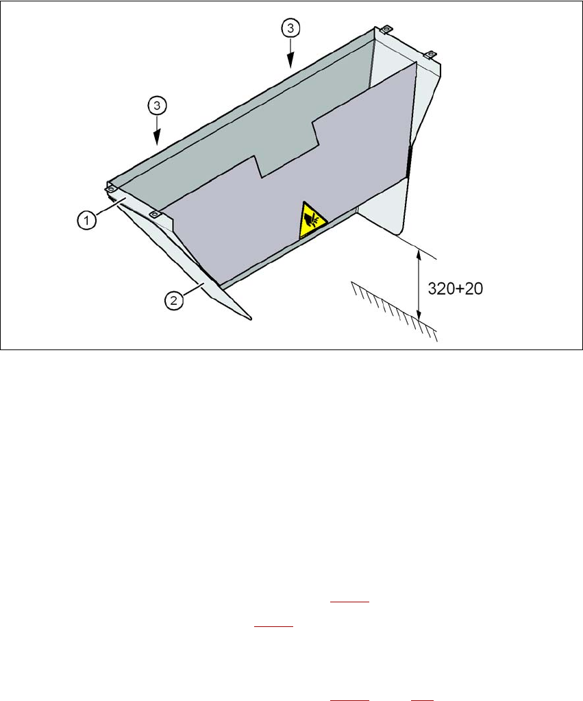
Fig. 4.5 - 1 Adapting the length of the used tape chute (X-series) - Dimensions in millimeters
(1) Used tape chute
(2) Extension
(3) Hexagonal nut M4, DIN 985, 2 x
4.5.1.1 Tools
– Fork wrench, size 7
4.5.1.2 Setting the used tape chute to PCB conveyor height of 830 mm
→ Loosen the two M4 hexagonal nuts (item 3 in Fig. 4.5 - 1).
→ Remove the extension (item 2 in Fig. 4.5 - 1
).
4.5.1.3 Setting the used tape chute to PCB conveyor heights of 900 mm - 950 mm
→ Loosen the two M4 hexagonal nuts (item 3 in Fig. 4.5 - 1, page 286).
User manual SIPLACE X-series Setting up and commissioning
From software version SR.70x.xx 01/2011 EN edition Adapting the used tape channel to the component height
287
→ Adjust the extension (item 2 in Fig. 4.5 - 1, page 286) so that the distance between the bottom
edge and the floor does not exceed 320 mm + 20 mm (see Fig. 4.5 - 1
, page 286).
4.6 Adapting the used tape channel to the component
height
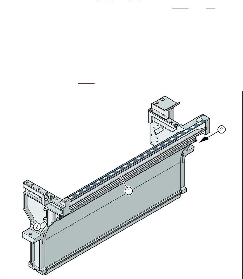
If X feeder modules are used, the component tapes work with a pocket height > 12 mm, so the
separating plate (item 1 in Fig. 4.6 - 1
) must be removed.
4
Fig. 4.6 - 1 Used tape channel, SIPLACE X-series
(1) Separating plate for tapes > 12 mm, removable
(2) DIN 93384 screw - M4x20, 2x