00196504-02_UM_X-Serie_SR70X_EN.pdf - 第212页
Setting up and commissioning User manual SIPLACE X-series Transport and Delivery Configuration From software version SR.70x.xx 01/2011 EN edition 212 4.1.4 T ransporting the machine in the crate 4.1.4.1 Services ASM Asse…
User manual SIPLACE X-series Setting up and commissioning
From software version SR.70x.xx 01/2011 EN edition Transport and Delivery Configuration
211
4
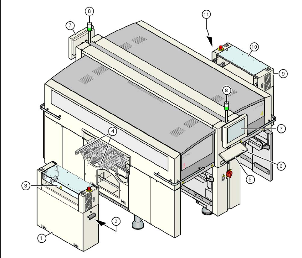
Fig. 4.1 - 2 Machine in the as-delivered configuration
(1) Extension kit on the PCB output side - detached for delivery
(2) Axis unit on the PCB output side - X4I, X4: gantries 2 and 3, X3: gantry 3, X2: gantries 1 and 3
(3) Conveyor cover
(4) Output conveyor
(5) Keyboard supporting plate
(6) Keyboard
(7) Monitor
(8) Indicator lamps
(9) Box PC unit on the PCB input side
(10) Extension kit on the PCB input side - may be removed if necessary
(11) Axis unit on the PCB input side - X4I, X4 and X3: gantries 1 and 4
Setting up and commissioning User manual SIPLACE X-series
Transport and Delivery Configuration From software version SR.70x.xx 01/2011 EN edition
212
4.1.4 Transporting the machine in the crate
4.1.4.1 Services
ASM Assembly Systems can fully integrate the X-series machines into your production line as a
service to you. With our extensive expertise and by using the right tools and equipment, we can
ensure that the installation process runs smoothly and efficiently. However, this will require you to
clarify the infrastructure aspects in advance and make any necessary changes at your production
facility.
Please note that the safest way to transport the machine is always in the transport crate - or at the
very least on the pallet. This will prevent serious damage to the machine caused by the feet col-
liding with obstacles, for example.
4.1.4.2 Safety instructions
WARNING 4
– The applicable accident prevention regulations concerning the transportation of heavy goods
must be followed.
– There is a risk that the machine will tip over if you do not use the fork-lift specified in Section
4.1.4.3
, page 212 to transport the machine.
– In particular, you should wear safety boots to minimize the risk of crushing your feet.
4.1.4.3 Means of transport
A fork-lift truck with the following specification will be needed to carry the machine on the pallet or
in its crate:
Fork length: min. 1800 mm
Carrying power: min. 6000 kg
Clear width between forks: min. 350 mm 4
4
User manual SIPLACE X-series Setting up and commissioning
From software version SR.70x.xx 01/2011 EN edition Transport and Delivery Configuration
213
4.1.4.4 Fork-lift attachment points on the transport crate or pallet
Attach the fork-lift only at the points identified by (A) in Fig. 4.1 - 1, page 209. We recommend that
you keep the crate or the pallet for later use.
WARNING 4
If you still decide to transport the machine without a crate or pallet, you MUST follow the instruc-
tions in the next section to avoid serious damage to your machine.
4
4
4
4.1.5 Transporting the machine without a crate or pallet
4.1.5.1 Safety instructions
WARNING 4
→ The applicable accident prevention regulations concerning the transportation of heavy goods
must be followed.
→ In particular, you should wear safety boots to minimize the risk of crushing your feet.
→ Read this section in full before transporting the machine to avoid severe damage.
→ When you are transporting the machine, make sure that all the feet are clear of the floor. If
they are not clear, the feet will drag along the floor and bump into obstacles. This could dam-
age the machine foot thread in the machine frame.
4.1.5.2 Means of transport
Use a fork-lift truck with the following specification to carry the machine:
Fork length min. 1800 mm
Lifting power min. 6000 kg
Distance between forks with the forks running parallel
to the direction of PCB transport
420 mm
Distance between forks with the forks running across
the direction of PCB transport
800 mm - 900 mm