00196771-04_IM_SSW_705_04_SP2_DE_EN.pdf - 第18页
Station Software 705.04 SP2 / Installation Manual Ausgabe 06/2012 Edition 4.2 SIPLACE X-, SX- and DX-series hardware components The following two diagrams sh ow the hardware components of the computer system for the SIPL…

Station Software 705.04 SP2 / Installation Manual Ausgabe 06/2012 Edition
--- CPPSZD
1)
Z-bottom, CPP head
--- WPCAXI
2)
WPC5 feed axis and lift axis
--- WPCHNG
2)
WPC5 / WPC6
--- DLMHED
3)
C&P12 head
Table 4-2: Names of the subsystems
1)
as of 702.xx
2)
as of 703.xx
3)
as of 705.03
17
Station Software 705.04 SP2 / Installation Manual Ausgabe 06/2012 Edition
4.2 SIPLACE X-, SX- and DX-series hardware components
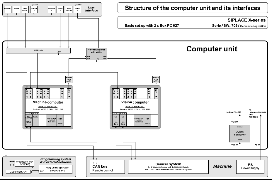
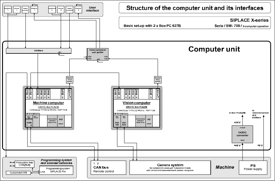
The following two diagrams show the hardware components of the computer system for the
SIPLACE X2, X3, X4 and X4I machines in two-computer operation:
Figure 4-1: Hardware components of the computer system for the SIPLACE X-series in two-computer operation (block
diagram)
18
Station Software 705.04 SP2 / Installation Manual Ausgabe 06/2012 Edition
Figure 4-2: Hardware components of the computer system for the SIPLACE X-series in two-computer operation (block
diagram)
19