00196578-03_AI_Pipettenwechsler_SX12_DE_EN.pdf - 第64页
2 Brief description 2.5 Required Working Time 64 Assembly Instructions / Montageanleitung SIPLACE SX1/SX2 Nozzle Changer Pipettenwechsler 06/2020
2 Brief description
2.4 Necessary tools
Assembly Instructions / Montageanleitung SIPLACE SX1/SX2 Nozzle Changer Pipettenwechsler 06/2020 63
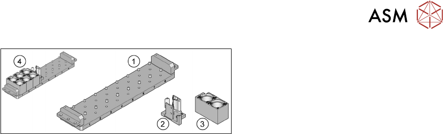
Fig.15: Nozzle changer TwinStar (short) [03062452‑xx]
1. Nozzle changer TwinStar (short)
[03062452‑xx]
2. Magazine for 1 nozzle [03001807-xx]
3. Magazine for 2 nozzles [03005191-xx]
4. Nozzle changer in standard configuration
1x magazine for 1 nozzle
3x magazine for 2 nozzles
2.4 Necessary tools
●
Set of Allen keys
●
Set of screwdrivers
●
Set of Torx spanners
●
Needle nosed pliers
●
Hammer
2.5 Required Working Time
The complete installation will take approx. 3 hours.
The machine standstill time is approx. 2 hours.
Programming work on the SIPLACE Pro computer may also be needed.

2 Brief description
2.5 Required Working Time
64 Assembly Instructions / Montageanleitung SIPLACE SX1/SX2 Nozzle Changer Pipettenwechsler 06/2020
3 Installation
3.1 Preparatory work
Assembly Instructions / Montageanleitung SIPLACE SX1/SX2 Nozzle Changer Pipettenwechsler 06/2020 65
3 Installation
3.1 Preparatory work
► Undock the component trolley.
► Switch off the machine, disconnect it from the power supply and secure it to prevent
unauthorized reactivation.
1.2 "Preparatory work..." [}50]
► Remove all nozzles and component reject bins from the relevant location.
► If a stationary camera is fitted at the relevant location, remove the upper part of the camera.
Make sure that the machine has been switched off for this!
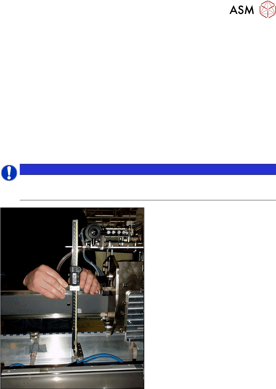
3.1.1 Setting the height of the nozzle changer
The contact surfaces for the NC basic structure at positions 1 and 2 are on the COT insert. The in-
stallation height is set via the shims and should be checked before assembly.
NOTICE
Scratching the magnetic strip
During the following inside measurement make sure that the tip of the measuring scale
does not touch the magnetic strip as this might scratch it!
Fig.16: Distance measurement
► Measure the distance between the con-
tact surface of the nozzle changer and
the guide rail of the gantry.
– The distance for standard gantries
must be 199.8+/‑0.2mm.
– The distance for 40mm gantries
with VHF must be 211.8+/‑0.2mm.
► Adjust the distance by inserting shim
plates (0.3 mm) where required.