00196578-03_AI_Pipettenwechsler_SX12_DE_EN.pdf - 第68页
3 Installation 3.3 Fitting the row 2 nozzle changer 68 Assembly Instructions / Montageanleitung SIPLACE SX1/SX2 Nozzle Changer Pipettenwechsler 06/2020 Fig.22: Fitted nozzle changer ► Insert the nozzle changer and fix i…
3 Installation
3.2 Fitting the nozzle changer
Assembly Instructions / Montageanleitung SIPLACE SX1/SX2 Nozzle Changer Pipettenwechsler 06/2020 67
Adjustment
► Set the correct value on the jumper for your head type, software and control method.
Jumper X10
Head SW <= 706.x SW >= 707.x
I/O controller XFCU I/O controller XFCU
CPx, DLM 1-2 1-2 1-2 2-3
C&P20P --- --- --- 2-3 (factory settings)
3.2.2 Installation
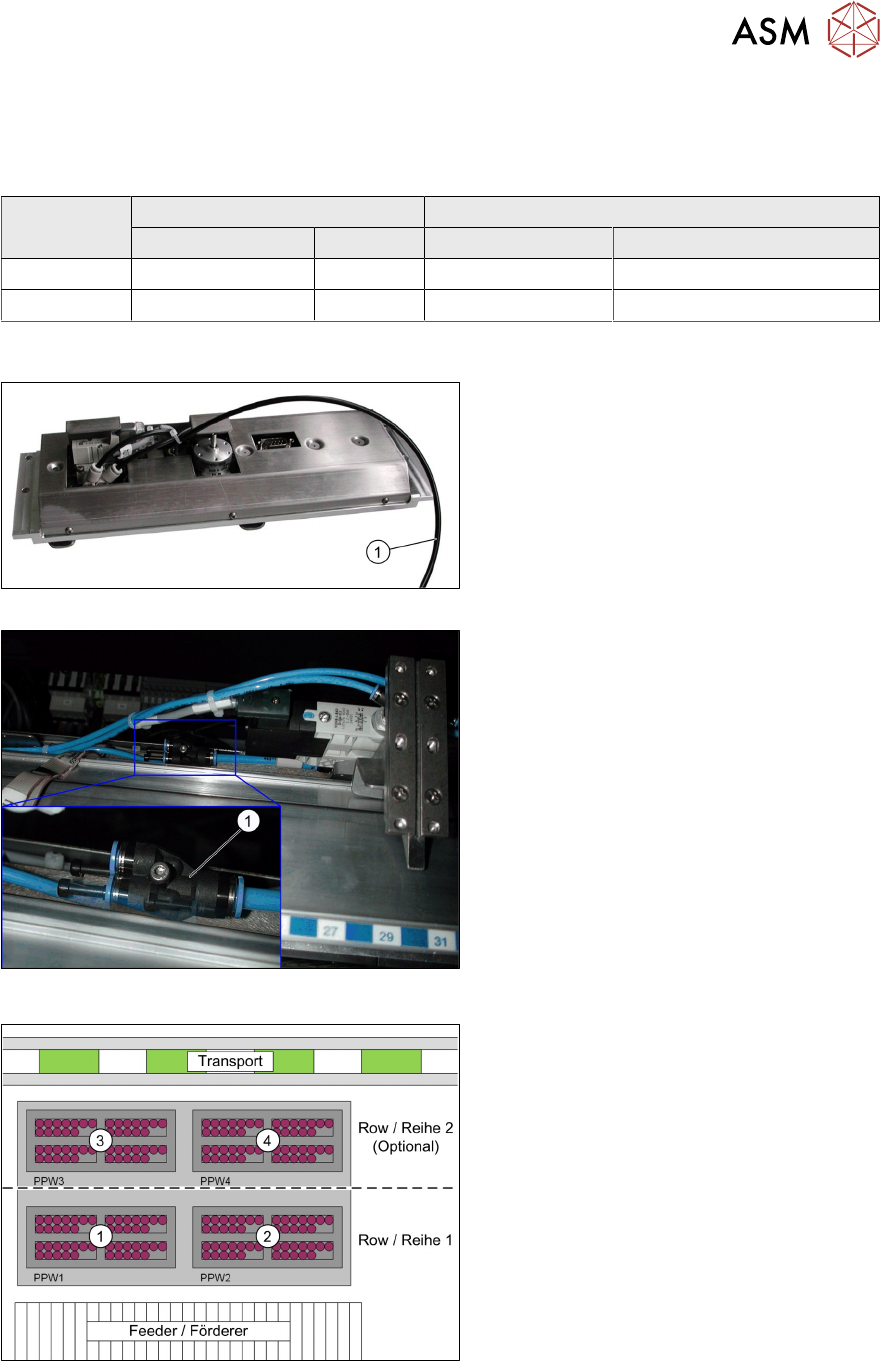
Fig.19: Compressed air hose
Fig.20: Compressed air hose connected
► Connect the compressed air hose(1) to
the nozzle changer.
The nozzle changer is supplied with
4.5bar air pressure.
Fig.21: Connections on the nozzle changer
► Connect the connection cable to the
nozzle changer according to the follow-
ing allocation:
1. Nozzle changer 1
2. Nozzle changer 2
3. Nozzle changer 3
4. Nozzle changer 4

3 Installation
3.3 Fitting the row 2 nozzle changer
68 Assembly Instructions / Montageanleitung SIPLACE SX1/SX2 Nozzle Changer Pipettenwechsler 06/2020
Fig.22: Fitted nozzle changer
► Insert the nozzle changer and fix into
place (four screws)(1).
► Fit the magazine onto the nozzle
changer.
3.3 Fitting the row 2 nozzle changer
When fitting the holder for the second row of nozzle changers, pay attention to the correct height
setting (see 3.1.1 "Setting the height of the nozzle changer" [}65]).
Fig.23: Holder center NC row 2 / SX [03066216-xx]
► Knock the locating pins (DIN 6325 -
5m5 x 20 x [00619868-xx]) into the cor-
responding holes in the holder.
Fig.24: Screws on holder
► Screw the holder into place as shown
in the diagram (screws ISO 4762 -
M5x16-A2-70 [03042562-xx])(1).
3 Installation
3.3 Fitting the row 2 nozzle changer
Assembly Instructions / Montageanleitung SIPLACE SX1/SX2 Nozzle Changer Pipettenwechsler 06/2020 69
Fig.25: Pins on the nozzle reject mount
► Knock the pins (DIN 6325 - 5m5 x 20 x)
[00619868‑xx](1) into the correspond-
ing holes in the holder "left NC row 2
assembly / SX" [03066001‑xx].
Fig.26: Screwing the holder into place
► Screw the holder into place as shown
in the diagram with the screws ISO
4762 - M5x16-A2-70 [03042562-xx](1).
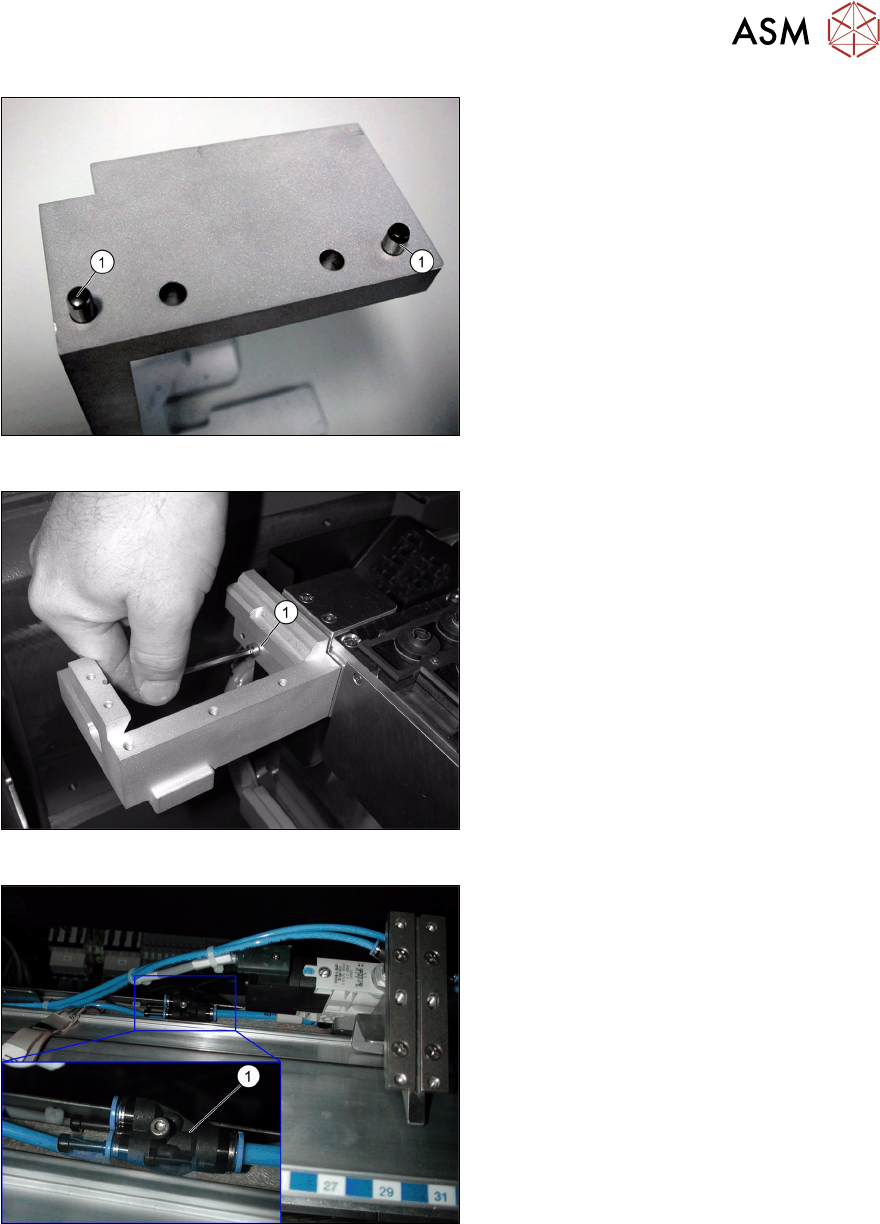
Fig.27: Compressed air connection
► Connect the second nozzle changer.
► Divide the compressed air hose and re-
connect the two nozzle changers with a
Y piece(1) to the compressed air sup-
ply.
► After fitting the "extension row 2 NC, check for the correct height (see 3.1.1 "Setting the height
of the nozzle changer" [}65]).
► Fit the NC into place with four screws (M5x14).