Plan_HF3_14_20_en line 1电路.pdf - 第163页
Pag e = + DE HF =HF +DG/1 29 Modificati on Date Na m e No rm Check. Proj. Origin Date Crea. f. Hot flow 3/xx =HF +DE/28 133 953- V00 Ot to-Schott-Straße 5 97 87 7 W ertheim Gm bH Plant designation Pr oj e c t name ERSA 1…
Page
=
+
DE
HF
=HF+DE/29
28
Modification Date
Name Norm
Check.
Proj.
Origin
Date
Crea. f.
Hotflow 3/xx
18.06.2009
=HF+DE/27
133953-V00
Otto-Schott-Straße 5
97877 Wertheim
GmbH
Plant designation
Project name
ERSA
14:15:2308.07.2010
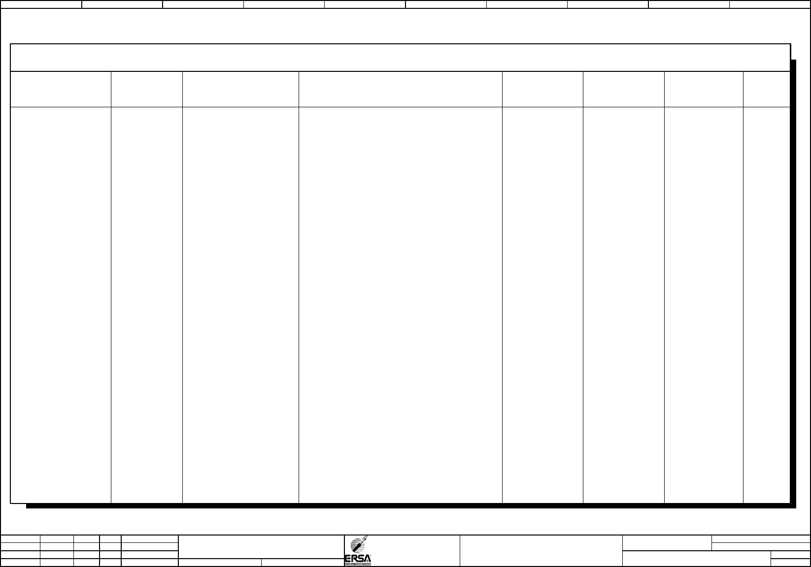
PLC-diagram
PLC
I/O
Function text
terminal
133953-V00
Project
PLC Designation sheet
Modul Modul
DIN_SPS_DIA_ERSA_LS
I/O-Info
=HF+C1-A100
IF2
=HF+C1/20.01 ethernet
0 0 -
=HF+C1-A100
IF3
0 0 -
=HF+C1-A100
IF4
0 0 -
=HF+C1-A100
IF5
0 0 -
=HF+C1-A100 IF1:11
0 0 1
=HF+C1-A100 IF1:12
0 0 2
=HF+C1-A100 IF1:13
0 0 3
=HF+C1-A100 IF1:14 =HF+C1/15.04 +24V supply CPU / X2X Link
0 0
14
=HF+C1-A100 IF1:15
0 0 5
=HF+C1-A100 IF1:16
0 0 6
=HF+C1-A100 IF1:21
0 0 7
=HF+C1-A100 IF1:22
0 0 8
=HF+C1-A100 IF1:23
0 0 9
=HF+C1-A100 IF1:24 =HF+C1/15.03 +24V supply I/O
0 0
24
=HF+C1-A100 IF1:25 =HF+C1/15.01 +24V supply I/O
0 0
25
=HF+C1-A100 IF1:26 =HF+C1/15.02
GND supply I/O
0 0
26
=HF+C1-A100
IF2
=HF+C1/900.01 ethernet
0 0
IF2
0 1 2 3 4 5 6 7 8 9

Page
=
+
DE
HF
=HF+DG/1
29
Modification Date
Name Norm
Check.
Proj.
Origin
Date
Crea. f.
Hotflow 3/xx
=HF+DE/28
133953-V00
Otto-Schott-Straße 5
97877 Wertheim
GmbH
Plant designation
Project name
ERSA
14:15:2308.07.2010
PLC-diagram
PLC
I/O
Function text
terminal
133953-V00
Project
PLC Designation sheet
Modul Modul
DIN_SPS_DIA_ERSA_LS
I/O-Info
=HF+C1-A100.1
IF1:1
0 0 1
=HF+C1-A100.1
IF1:2
=HF+C1/355.02 CAN_L
0 0 2
=HF+C1-A100.1
IF1:3
=HF+C1/355.01 SHLD
0 0 3
=HF+C1-A100.1
IF1:4
=HF+C1/355.02 CAN_H
0 0 4
=HF+C1-A100.1
IF1:5
0 0 5
0 1 2 3 4 5 6 7 8 9
Page
=
+ DG
HF
=HF+DH/1
1
Modification Date
Name Norm
Check.
Proj.
Origin
Date
Crea. f.
schb
Hotflow 3/xx
18.06.2009
=HF+DE/29
133953-V00
Otto-Schott-Straße 5
97877 Wertheim
GmbH
Plant designation
Project name
ERSA
14:15:2308.07.2010
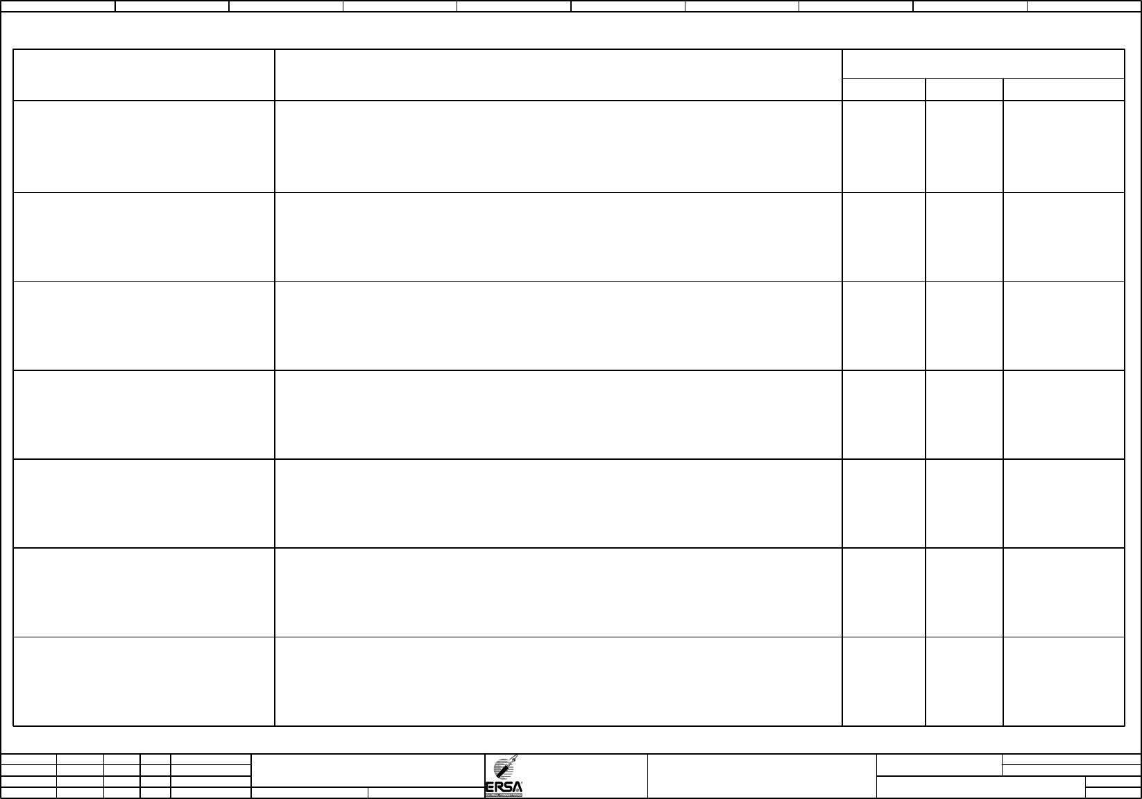
terminal strip overview
Terminal strip overview
Terminal strips / Connectors
Sum PE
Function text
Sum N
DIN_KLU_35_ERSA_LS1
Terminals
=HF+C1-X1 PE terminal energy
3 2 8
=HF+C1-X2 230VAC-terminal basic 16 17 49
=HF+C1-X5 24VDC-terminal basic
1 0
209
=HF+C1-X5.3 24VDC-terminal conveyor-system CAN
0 0
136
=HF+C1-XF1 supply-terminal thre-phase-current prefuse 35mm²
0 0 3
=HF+C1-1X2.1 230VAC-terminal heatings 1-7 top
7 0
21
=HF+C1-1X2.2 230VAC-terminal fans 1-7 top
1 0 7
=HF+C1-3X2.1 230VAC-terminal heatings 8-10 top
5 0
15
=HF+C1-3X2.2 230VAC-terminal hfans 8-10 top
1 0 7
=HF+C1-4X2.1 230VAC-terminal heatings 8-10 bottom
9 0
27
=HF+C1-4X2.2 230VAC-terminal fans 8-10 bottom
1 0 9
=HF+C1-7X2.2 230VAC-terminal fans cooling zone
7 0
38
=HF+C1-9X2.1 230VAC-terminal heatings 1-5 bottomoption preheating bottom
7 0
21
=HF+C1-9X2.2 230VAC-terminal fans 1-5 bottomoption preheating bottom
1 0 7
=HF+C1-22X5.1 24VDC-terminal emergency stop
0 0 8
=HF+C1-41X5 24VDC-terminal option SMEMA interface 1
0 0
15
=HF+C1-42X5 24VDC-terminal option SMEMA interface 2
0 0
15
=HF+C1-43X5 24VDC-terminal option WMW interface 1
0 0
24
=HF+C1-44X5 24VDC-terminal option WMW interface 2
0 0
24
=HF+C1-47X5 24VDC-Klemmleiste option SMEMA interface 3
0 0
15
=HF+C1-48X5 24VDC-Klemmleiste option SMEMA interface 4
0 0
15
=HF+C1-XPE1 PE-Terminal energy meassuring
0 0 1
=HF+C1-7X2.1 230VAC-terminal heating controled cooling zone
1 0 3
0 1 2 3 4 5 6 7 8 9