HOST.pdf - 第39页
BM 122/ 123 /1 33/ 221/2 31 HOST COMPUTER SYSTEM 3.4 R Comm ands E35HEC- 4A-191- A0 3.4- 2 Ex. : Produc tion tim e tot al Ex. : Real-tim e command at EOP The f oll owing shows inf orm ation for EOP operati on f rom the h…
BM122/123/133/221/231
HOST COMPUTER SYSTEM
3.4 R Commands
E35HEC-4A-191-A0
3.4-1
3.4. R Commands
E35HEC-4A-191-A0
R commands are optional.
These commands are used to notify production quantity information, operation mode information and error
information from the machine to the host computer.
Item Description
Command name Sending the changes in machine status
COM port used Port 2
Data format
Item Description
Command field R0 + Machine status
R1 + Processing information Output one of these
R2 + Error information R commands
R3 + Recovery information
Data size field 0
Data field None
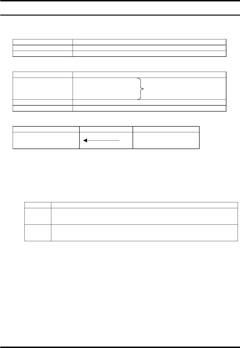
Command sequence
Host computer system Equipment
End (1) R0 to R3 + data
(1) No data type (2) Data-attached type
It is not necessary for the host computer to respond with A2 command to the R command received.
3.4.1 Production Quantity Information: R0CT / R0EP
R0 commands are used for totaling the time of operation started by the remote control command.
Command format: R0∗∗Cnnnn
∗∗ Code Application
∗∗
Description
CT
Generated when product program EOP block execution is complete and stop mode is
‘CONT’.
Usually, it is used to count PCB production.
EP
Generated when stop mode is ‘EOP’ or ‘1. BLOCK’ and product program has executed
an EOP block.
This signal can be used for production complete. At this time, R0CT is not output.
nnnn:
Outputs the production time per board (incl. loading) in seconds.
It is possible to switch whether or not to output production time per board.
== Refer to ’3.4.6 Setting R Commands Output Condition’ for details.
These real-time information are used for totaling production time as shown in the following example.
BM122/123/133/221/231
HOST COMPUTER SYSTEM
3.4 R Commands
E35HEC-4A-191-A0
3.4-2
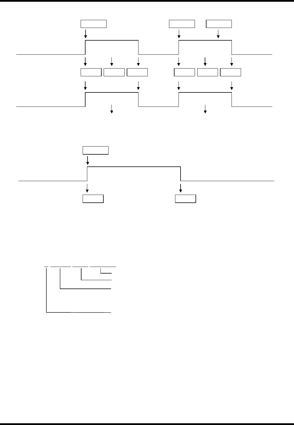
Ex.: Production time total
Ex.: Real-time command at EOP
The following shows information for EOP operation from the host computer.
3.4.2 R0BD
This command is used to notify the result of bad mark recognition.
Command format:
C5STEP
R1ST
Machine Operation Status
(EOP or 1 block operation)
R0EP
Machine automatically stops
R 0 B D G
S m m m Z n n n M 0 T 0 0 0
Fixed character string
Z No. (Not used, fixed at 000)
Number of the pattern the bad mark belongs to.
Smmm is not output if the program is not for multiple-pattern
boards.
‘G’: Recognition was successful.
‘NG’: Recognition was unsuccessful.
C5STCT
R1ST R0CT R2E03
Control command
Machine Operation Status
(CONT Operation)
Real-time command
EOP block
Component
exhaust
EOP block
R1ST R0CT R0EP
EOP stop
C5ST C5SPEP
Production time total
Count up Count up
Production Board Count
BM122/123/133/221/231
HOST COMPUTER SYSTEM
3.4 R Commands
E35HEC-4A-191-A0
3.4-3
3.4.3 Operation Mode Information: R1
The R1 commands are used to notify the host computer that the control switches located on the machine
have been used by either the operator or host computer.
Command format: R1∗∗
∗∗ Code Application
OL or FL
These commands notify the host computer that the operation mode of the machine is either online (OL)
or offline (FL).
Remote mode is engaged only when the operation mode is AUTO and the communications mode is
REMOTE. In other cases, the ONLINE mode is set.
These signals are generated when the mode switches on the control panel of the machine have been
operated, or when power has been switched on.
ES
When the power is shut down by an emergency stop, etc., R1ES command is output.
ST
This command is used to inform the host computer that the machine has started because the START
switch on the control panel was pressed or a C5ST command was input from the host computer.
This signal is also output at the time of restart.
SP
This command shows that the machine has stopped in conditions other than error.
Specifically, it is a normal stopping of 1 block operation other than at the final mounting block.
When the step of the product program is EOP, an R0EP command will be output instead of this
command to distinguish the stop from the one in the EOP mode.
RE
This signal is output when the RESET switch on the control panel has been pressed by the operator or
when a C5RE command has been executed by the host computer.
PS
This command is output when a PC board has been loaded onto the loader and the stage is ready for
loading.
PW
When placement of the current PC board is completed, each axis returns to origin and a new PC board
is loaded to the mounting position.
If there is no PC board on the loader (that is if R1PS command has not been issued previously), the
machine must wait for arrival of a PC board and this command is output.
This signal is sent also if the finished board at the mounting position cannot be unloaded onto the
unloader.
PE
This signal is output when a PC board has been loaded onto the loader or unloaded onto the unloader
after an R1PW command.
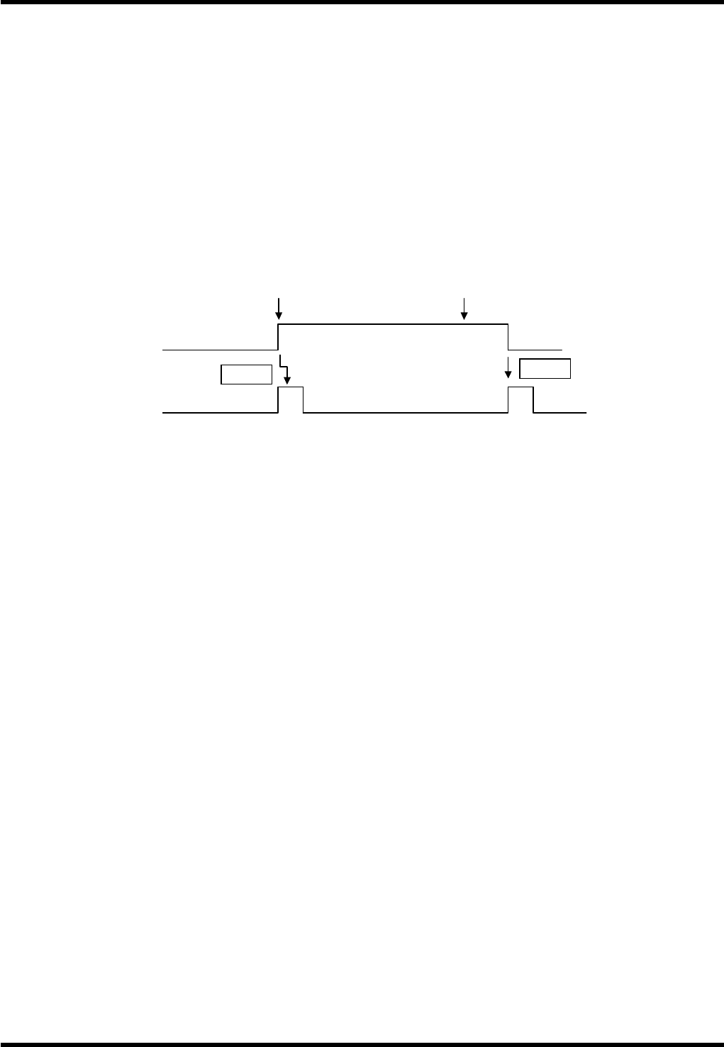
R1FL
‘power on SW’ ON
Input power source
R1ES
‘Emergency Stop SW’ ON